Teardown: Dissecting Lenovo’s Smart Clock Essential, a non
- LEDS
- 2023-09-23 23:13:26
Smart devices are an increasingly common presence in residences, often in multiples per address, and ranging from audio-centric smart speakers (also with microphones) to more capable screen-inclusive (and sometimes also camera-inclusive) products. Branded examples of the former include Amazon’s various audio-only Echo devices and Google’s Home (now Nest) products, along with Apple’s HomePod Mini (supporting the company’s Siri technology). And in the latter camp are Amazon’s Echo Show and Google’s Home (again, now Nest) Hub variants.
Both Amazon (with Alexa) and Google (with its Assistant) have also strived to gain support for their “smart” ecosystems within other companies’ products, with varying degrees of success. Lenovo is a particularly curious example. To date, it’s developed two generations’ worth of the Smart Clock Essential, a voice-controllable “clock radio on steroids.” Lenovo has also developed two generations’ worth of the higher-end Smart Clock, which adds touchscreen support, but whereas both Smart Clock generations support Google Assistant, the company switched from Google Assistant (Gen 1) to Amazon Alexa for the just-introduced Gen 2 Smart Clock Essential.
Equally curious to me is the fact that Lenovo is a China-headquartered (albeit international) company; many Google services are blocked by China’s Great Firewall. And finally, while ordinarily the differential between bill-of-materials (and other) costs and price is the definitive determinant of profit or loss for a consumer-electronic device, in these cases, I suspect Amazon and Google may be subsidizing their partner’s (Lenovo’s, in this particular instance) products’ costs as a means of expanding their ecosystems.
To wit, today’s teardown victim is the first-generation Smart Clock Essential, which I bought refurbished late last summer from VIPOutlet via eBay for under $18. Similarly, shortly before I began writing this, Best Buy had them on sale, brand new, for $25. I’ll start with a “stock” photo:


And here is a promo video:
Since mine was a refurb, it arrived already de-boxed, albeit still with a protective sheet of plastic over the 4-inch (10.2-cm) diagonal front. Here it is accompanied by its “wall wart” and an as-usual 0.75-inch (19.1-mm)-diameter U.S. penny for size-comparison purposes (the Smart Clock Essential has dimensions of 4.8 × 2.5 × 3.3 inches [121 × 64 × 83 mm] and a weight of 11.6 oz. [328 g]):

And here’s a close-up of the specs of the “wall wart”:

Overviews of the back and sides of the unit show off its attractive (IMHO, at least) grey fabric cover for the white plastic chassis underneath:


Let’s now focus in on the top:

Since the Smart Clock Essential (unlike its Smart Clock bigger sibling) doesn’t include a touchscreen, Lenovo added physical buttons for:
Volume up/downPlayAlarm (on/off)You can supposedly also snooze the alarm by tapping anywhere on the top, although I was unable to discern definitively how this latter capability is implemented. My guesses are either via an accelerometer (they’re tiny, so perhaps it’s there and I just couldn’t locate it) or through sound picked up from the front-mounted microphone array. In the latter case, the microphone mute switch would seemingly defeat the function, although it appears that whatever the “tap” sensor is, it seemingly works in conjunction with the ambient light sensor (which may temporarily override “mute”). Speaking of which, here’s the mute switch, among other things:

To its right is a USB charging port for a tethered smartphone or other device; the Smart Clock Essential gets firmware updates over Wi-Fi. And on the left is the power input.
Now let’s turn the device upside down:

Both rubber “feet” have markings on them, including but not limited to the all-important (for research purposes) FCC ID, O57CD4N341Y. Those “feet” were my first-attempt path to the inside of the device, which proved fruitless. So I turned my attention to the front, aided by a thin, flat-head screwdriver:

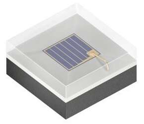
Already visible are the two microphones at top, with an ambient light sensor between them and toward the left side, and, of course, the array of LEDs. The “screen” in this case is just a translucent piece of plastic. Speaking of LEDs, and before going further, I thought I’d temporarily connect power to the device and show you what the boot-up sequence looks like:


At the end, there’s also an audible notification via the system’s 1.5-inch 3-W speaker to connect the device to the Google Home app on a Bluetooth-equipped mobile device to complete setup:
Removing the four Phillips screws seen in the earlier photos was a seemingly obvious next step forward, but it initially only led to frustration: Not only could I not then disconnect the two wiring harnesses shown here, I couldn’t ascertain how they’d ever gotten connected during initial system assembly in the first place:

But then I realized that the assembly to the right in the previous photo was actually a two-level “sandwich”:

Already visible on the display PCB is (among other things) an IC labeled:
V11103112
It’s located alongside the PCB marking “SN3112,” which I’m guessing references a 12-channel LED controller from Si-En Technology. Also visible are two TM1652 LED driver ICs from Shenzhen Titan Micro Electronics, one on either side of the PCB. I’ll save a pry-away of the Faraday cage on the system PCB for later.
Although the partial disassembly I’d done was enlightening, further progress was still hampered by the aforementioned cabling. Clearly there was another approach still necessary to fully get to the insides, so I redirected my flat-head screwdriver’s attention to the back side. Initial efforts were again frustrating, until my twisting inadvertently revealed that the back panel was actually a two-piece assembly:


Removing the now-exposed two Philips screws got me where I next needed to be:


At this point, you might be wondering if you’re seeing things. Allow me to reassure you that your eyes and brain are indeed functioning correctly; that really is a ring of LEDs, which shine through the translucent rear end, implementing a user-controllable–intensity “night light”:

Inside-access mystery solved, let’s proceed:

The chassis isn’t particularly memorable—plenty of holes for both the speaker’s sound and any system-generated heat to escape:

What’s inside the chassis is, unsurprisingly, much more interesting. Back side first; there are those LEDs again, now more clearly discernible:

Next, the left side, showing an interesting wire-connected “sticker” (hold that thought):

And the right side, providing a peek at those two front-to-back wiring harnesses:

The bottom view is dominated by an odd-looking mesh “strap” (again, hold that thought):

Now, let’s have an initial look at the four top-mount switches, along with that earlier-mentioned speaker:

And now let’s get the speaker out of there:

Disconnect the cabling from the system PCB and you can look at the transducer standalone:


One more cord left to sever:

And the rear and system PCBs are now free from their previous shared captivity:

Not much to write home about on the now-visible rear PCB back side, at least for now (once again, hold that thought):

And I’ve admittedly spoken too soon re: the system PCB: There’s one more wire harness (which is at least reminiscent of, if not in reality, an antenna connection) to go:

Before continuing, let’s take another peek at those switches from a different vantage point:

Here’s the now-fully visible back side:

Already notably identifiable are (left to right) the:
AP6256 802.11ac/a/b/g/n dual-band 1T1R Wi-Fi and Bluetooth 5.0 SiP module, based on Broadcom’s BCM43456 combo chip (which ironically, considering my earlier clock radio analogy, also supports FM band reception)Amlogic A113X system SoCElite Semiconductor Microelectronics Technology (ESMT) AD52058 Class D audio ampRemove the Faraday cage and another chip underneath it comes into view:

A Micron IC is labeled:
9YP77D9SHD
Which, as it turns out (see the “FBGA Code” entry), is the MT41K256M16TW-107, a 4-Gbit DDR3-1866 SDRAM.
Turn the system PCB over:

Pull off its Faraday cage and what you’ll find underneath isn’t terribly exciting, either:

A Macronix MX30LF4G28AD-TI 4-Gbit SLC NAND flash memory. Why Lenovo chose to place the two discrete memory devices underneath Faraday cages in this design versus other circuitry (or, for that matter, nothing at all) is admittedly baffling to me.
We’re in the home stretch, but there are a few more things I want to show you. Returning to the now-PCB-less main assembly:

Removing the strip of tape along the top didn’t do anything meaningful. More generally, the aluminum portion is stubbornly glued in place. That said, there’s nothing notable left in the interior anyway. But the exterior still contains a couple of curiosities:

That grounding strap (I’m guessing that’s what it is—readers?) first, which I’d briefly mentioned earlier, extends from the back to the aluminum plate at the front, where it’s glued in place. At the back, it ends at a “pad,” for lack of better words (detail-oriented readers may have already noticed another stuck to one of the 24 solder-point arrays on the front of the system PCB):

Here’s my guess as to this particular pad’s function (again, readers, your conjectures are also welcome). The back-side positioning of that “pad” coincides with the location of a 15-solder-point array on the rear PCB. My supposition is that the 15-contact array finds use directly and/or in conjunction with a potentially initially enhanced-function USB connector on that same PCB, for testing and final programming (language support for a particular end market, for example) during system manufacturing. Once those steps are complete, the back PCB is placed in its final position, in the process grounding the solder points and precluding any further unintentional ESD- or otherwise-induced signal activations.
Now for that foam- and glue-covered cable that routes from the antenna-reminiscent connector on one end of the system PCB to a sticker on the assembly’s other side:

Indeed, it’s an antenna:

The Smart Clock Essential, reflective of the Broadcom BCM43456 inside it, is specified to support both the 2.4-GHz and 5-GHz Wi-Fi bands, along with 2.4-GHz Bluetooth. How a single antenna spectrally accomplishes all of this is something I’m admittedly baffled about. I didn’t see any visual evidence of additional PCB-embedded antenna structures (which might, for example, find use for the short-range Bluetooth-based initial pairing function—the device can’t be used as an elementary Bluetooth speaker, so long-range reception isn’t strictly necessary).
Finally, let’s return to the front assembly. First step is to remove that mini PCB (disconnecting it from the ambient light sensor in the process):

The dual MEMS microphones come into clear view:


All that’s left is to carefully apply a bit more “elbow grease” to separate the LED-array PCB from its white plastic surroundings:


And that’s a “wrap” on another more-interesting-than-initially-expected teardown! Reader questions and thoughts are, as always, welcomed in the comments.
—Brian Dipert is Editor-in-Chief of the Edge AI and Vision Alliance, and a Senior Analyst at BDTI and Editor-in-Chief of InsideDSP, the company’s online newsletter.
Related Content
Teardown: Google Home smart speakerTeardown: Google’s Home MiniTeardown: Prying open Google WifiTeardown: Amazon Echo Dot gets improved sonic performanceTeardown: Google Home Hub smart speaker and displayTeardown: Dissecting Lenovo’s Smart Clock Essential, a non由Voice of the EngineerLEDSColumn releasethank you for your recognition of Voice of the Engineer and for our original works As well as the favor of the article, you are very welcome to share it on your personal website or circle of friends, but please indicate the source of the article when reprinting it.“Teardown: Dissecting Lenovo’s Smart Clock Essential, a non”


