Power Tips #93: Reduce voltage variation with weighted voltage feedback
- LEDS
- 2023-09-23 23:13:56
Transformer-derived topologies such as the flyback allow power supplies to easily create multiple output voltages by adding secondary windings to the transformer. This creates a situation where you must choose which output voltage to regulate, which is not always easy. It might be the output with the highest power, or a low-voltage output that requires tight regulation.
Once you have chosen an output, this voltage is used as feedback to the controller. Direct feedback provides excellent regulation on only that particular output and leaves the other output (or outputs) “loosely” regulated. In many cases, the unregulated voltage may vary over an undesirably wide range, largely based on the transformer’s leakage inductance. To tighten up the regulation, one possible solution is to increase the voltage and add a linear regulator. But that adds cost and heat, and lowers system efficiency. In this power tip, I’ll investigate the use of a dual resistor divider network that enables two output voltages to share the voltage regulation.
Figure 1 shows a simplified schematic of a flyback converter with dual outputs. Output voltages V1 and V2 feed into a two-way resistor divider that the controller uses for feedback. This method is commonly referred to as “weighted averaging” because each output voltage has some contribution to the controller’s duty cycle. The effective outcome is that each voltage can vary based on the percentage of current that flows in the resistor connected to each output (R1 and R2) relative to the total in R3. If the majority of R3’s current flows in R1, output V1 will vary the least—as it is weighted heavily—whereas V2 may vary significantly. If each output voltage sources half of R3’s current, then each output voltage should vary by about the same percentage. Voltage regulation at extreme load differences is, however, heavily dependent on transformer leakage inductance, component parasitics and even printed circuit board layout. Thus, you can expect some deviation.
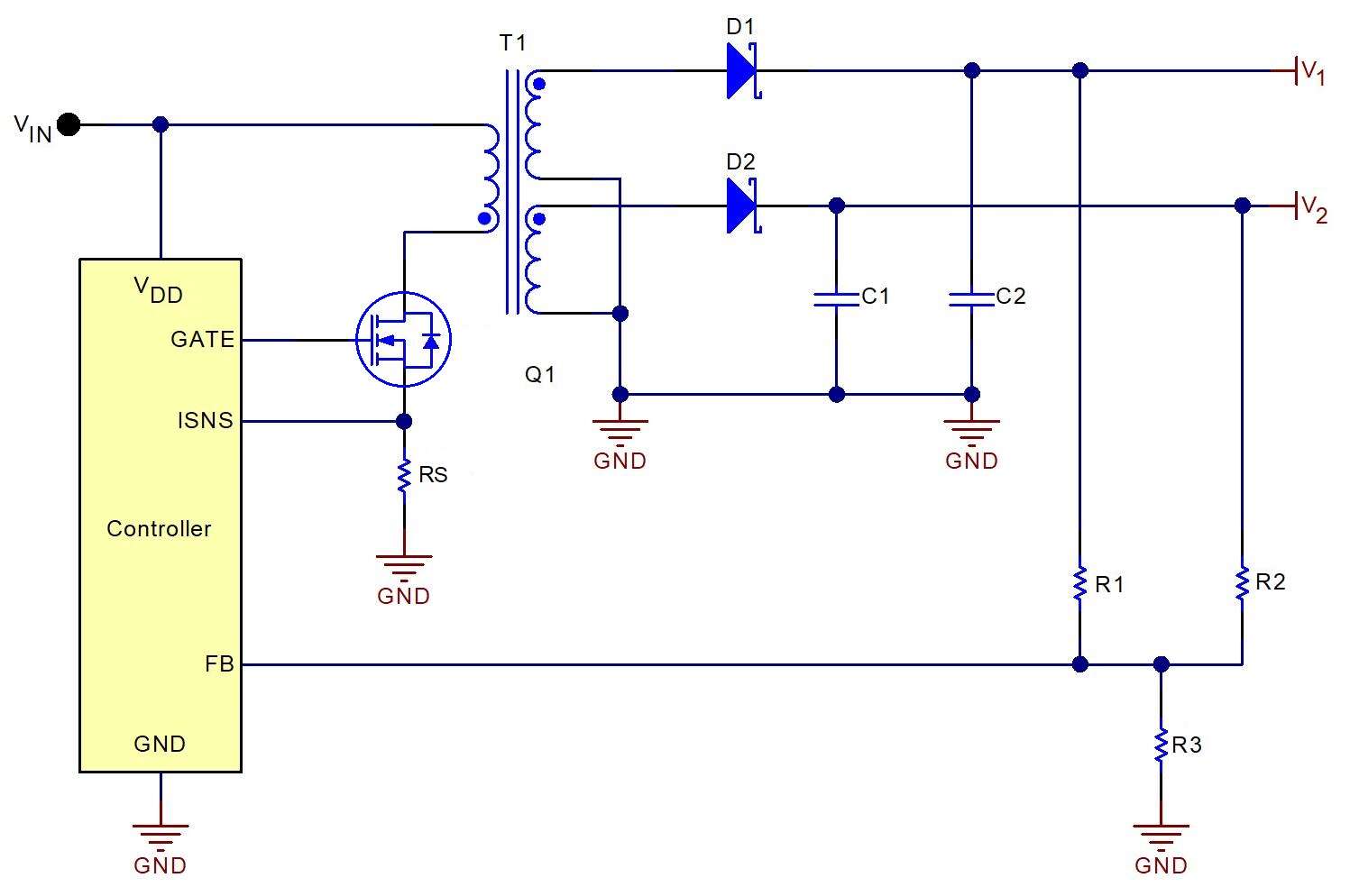


The most common application for weighted averaging would be to loosen up one voltage in order to tighten up the other. For example, rather than have one voltage with ±3% tolerance (regulated) and the second ±20% (unregulated), it might be preferred to have each vary ±10%.
Determining the values for R1, R2 and R3 simply requires that you have a weight percentage goal in mind based on the balancing required of the two outputs.
Follow these steps to select divider resistors R1 and R2:
Choose a desired value for R3.Calculate the current in R3:


Figure 2 plots four calculated regulation lines for the dual feedback network shown in Fig. 1. The lines plot possible output voltages based on the equation in step No. 6 above. In this example, the nominal output voltages for V1 and V2 are 3.35 V and 9 V, respectively, which are determined by transformer T1’s turns ratios. The four lines represent weights assigned to V1 equal to 100%, 90%, 70% and 50%. A weight of 100% is the same as using a single output voltage for regulation. Since a weight of 100% on the 3.35-V output does not consider the second output, the plotted line is horizontal and the 9-V output varies independently.

For the other three regulation lines, only specific sets of regulation voltages satisfy the controller’s feedback. If an output is heavily loaded, its voltage will tend to sag from increasing voltage drops. If the second output is lightly loaded, its output voltage may float much higher than its nominal value. This creates a situation where one output is lower than nominal, and the other is much higher.
As usual, the controller attempts to compensate by adjusting the duty cycle, which forces both outputs either higher or lower together. The current in R3 adjusts until the feedback voltage is equal to the controller’s internal VFB reference voltage and both output voltages intersect with a point on the regulation line. For balanced loads and a low leakage transformer, the voltages will tend to stay near the convergence point of the curves, close to their nominal values. However, extreme cross-loading on the output voltages, along with loosely coupled transformer windings, will push the regulation voltages further away from nominal.
Figure 3 shows measured data from a flyback converter similar to that shown in Fig. 1. The plotted data closely matches the calculated data of Fig. 2, with only minor variations largely due to resistor and VFB tolerances. Each plotted line consists of four data points representing the four possible output voltage loading extremes on a two-output converter (maximum/maximum, maximum/minimum, minimum/maximum and minimum/minimum). Balanced loads (that is, maximum/maximum and minimum/minimum) provide tighter regulation and lay near the center portion of the lines. The end points represent the regulation limits at maximum/minimum and minimum/maximum conditions. In this example, minimum was no load. This loading determines the outer boundary for output voltage tolerances. Comparing the plotted lines, you can see that heavier weighing tightens the tolerance on one voltage at the expense of the other.

Budget constraints don’t always let you design precision regulation into each output voltage in your multi-output converter, but some output voltages may not require tight regulation. For example, field-effect transistor gate drivers may work with voltages as loose as ±30%. With the addition of one resistor, you may be able to bring a very loosely regulated voltage back into specification if you can allow another to have a wider tolerance. Thus, the lossless technique of weighted averaging on a multiple output converter can be another useful tool in your power-supply toolbox.
John Betten is an Applications Engineer and Senior Member of Group Technical Staff at Texas Instruments.
Related articles:
Crossing the boundary: strategies for feedback across an isolation barrierHeavy-duty power supply regulates either voltage, current, or power by Jim WilliamsPower supply “Remote Sense” mistakes & remediesThe inductive nature of voltage-control loopsHow to verify control loop designDesigning a stable DC/DC control loopLoop tuning controls transient response in point of load power modulesEasier tuning for load transient in power supplies for high power CPUsPower Tips #93: Reduce voltage variation with weighted voltage feedback由Voice of the EngineerLEDSColumn releasethank you for your recognition of Voice of the Engineer and for our original works As well as the favor of the article, you are very welcome to share it on your personal website or circle of friends, but please indicate the source of the article when reprinting it.“Power Tips #93: Reduce voltage variation with weighted voltage feedback”