Proposed LED/wired IoT standard can reduce energy use (part 3)
- LEDS
- 2023-09-23 23:14:00
In Part 1, we looked at how to remove AC/DC converters from LED bulbs to save energy. Part 2 covered home lighting networks and communications.Here we’ll dive into solar, wires, connectors, and bulb design.
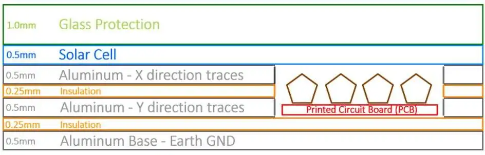
Do you want to save energy? Consider solar IoT. This is when your photovoltaic solar system is connected to the local area network and is modeled as another IoT device that supplies power. In this concept, solar material is laminated with multiple layers, like a PCB. Figure 11 shows a side view of a solar laminate.
In a top view (Figure 12 ), embedded PCBs are pictured in red and metal conductors shown in gray and light blue. Our base material is sheet aluminum. Subsequently, this can be mounted directly onto a building external surface such as a plywood roof or wall. For details, see R&D Initiative looks to solve energy and climate problems.


Figure 13 shows a closeup of our PCB and how it can attach to different voltages created by the solar material. Each cell is like a battery, and the PCB can combine these in series or parallel through MOSFET switches. We get programmable DC voltages from our solar IoT device.

Electrical connections Power wiring connections are typically done with screw force, where a screw head presses against a wire with thousands of pounds per square inch of force (Figure 14 ). This creates reliable connections that last 100 years. Alternatively, a pin pushed into a socket and held in place with spring force is less reliable, especially when handling power.

A connector that supports screw force with multiple contacts and is quick to install is required. Below is one such idea. The illustration on the right shows a screw pressing against a wedge (red), which in turn applies pressure against a sliding block (Figure 15 ). The illustration on the left shows how a screw can apply tremendous force (relative to spring force) against multiple blades from the socket with insulation (blue) in-between each signal. The kink shown in the blades makes it difficult for the plug to disconnect after the screw has been tightened. This connector could be placed inside light sockets and end user on/off/dimmer switches housings, for example.

Ribbon cable with four or six conductors might fit nicely into a crimping tool that attaches the above blade contacts to wire in one squeeze (Figure 16 ).

Tomorrow’s electrician could move more quickly with a motorized machine the size of a hand drill that mills plastic and electrically rotates screws, as shown in Figure 17 . Such a machine grips a cable, identifies its size, and mills plastic to expose wires. A clamshell clamp on each device secures the entire cable, and individual screw clamps make contact with each wire. This machine also turns screws and applies required torque. Subsequently, we can touch each device without cutting cable, which saves time and increases reliability. If an electrician costs $75/hr, then a sophisticated machine that saves time could easily pay for itself.

The proposed LED bulbs also support standalone systems that are not connected to the network, as Figure 18 shows.

Diffusers and shade accessories Traditional bulbs were originally designed to accommodate significant heat due to internal incandescent filaments. In our shrunken LED-only form, we can place bulbs flush against a surface, with a small standoff distance for cooling. Figure 19 shows a drywall ceiling (black), 2×4 wood framing (brown), metal electrical box (dotted blue), and a light socket fixture (dotted orange).

In Figure 20 , we have a flat surface between the bulb and socket (light green). What can we do with this? Conduct heat from bulb to socket? Support aftermarket track lighting-like directional support mechanisms, as illustrated in Fig. 19? If we add strength to the socket to resist added torque from aftermarket accessories, they also add cost. This is one issue that mechanical engineers would need to consider. In many buildings, bulbs are placed into recessed cavities within a ceiling. This makes a bulb less visible and obtrusive to the user. Fig. 20 shows an example of an aftermarket accessory that has a similar effect. Alternatively, one could also add a larger dome to better distribute light.

Because we are working on a new electrical standard, we have the luxury of adding a standardized mechanical region to grip diffuser and shade accessories. The blue lines shown in the Fig. 20 shade accessory fit into a region controlled by an LED mechanical standard and required by all bulbs and all sockets. Figure 21 shows how track lighting would work.

Heat and the national electrical code Moving heat and conforming to building codes deserves more consideration (e.g. National Electrical Code, Underwriters Laboratories). One option is to rely on the socket to help dissipate heat, since it is affixed to something larger than a bulb and has more surface area than a bulb. Heat can easily travel from LEDs to a metal socket due to close proximity. To help avoid fire, one could place a MOSFET switch inside each bulb that opens if too hot (e.g. at 105°C). To reduce cost, one would want to wire from a central location in a room (e.g. occupancy sensor in ceiling) to each bulb and possibly each window, without a conduit.
Power supplies embedded in a traditional light bulb base are subject to extreme heat; components such as electrolytic capacitors don’t last long under these conditions. A typical lifetime specification for an electrolytic capacitor is 2000 hours at 105°C. LED SMT devices dissipate approximately 85% of the heat inside a bulb, which means they get very hot (e.g. 8.5 W with 10 W bulb). Subsequently, moving electrical parts further from LED SMT devices reduces their operating temperature, and increases their longevity.
One heat strategy is to clamp a thermally conductive bevel/reflector/molding/heat sink device between bulb and socket, as shown below in blue in Figure 22 . A thermal gasket between bulb and socket provide thermal contact while tightening against a central electrical conductor. Alternatively, we could place a spring at the central electrical conductor and avoid a thermal gasket between bulb and socket.

Getting all this to work requires a standardized plug-and-play solar IoT system that includes mechanical standards, electrical connection standards, and communications protocols. Manhattan 2 is an example of an organization that is working on this, and is in the process of designing a 2000 square-foot test site in which we can test solar IoT, direct to building surfaces, with other IoT-like devices. A location for this site has not yet been determined. For more details, see Manhattan 2’s Wired-IoT R&D Plan and Solar Direct to Surfaces R&D Plan.
Glenn Weinreb is founder and CEO of GW Instruments and has designed approximately 30 commercial data acquisition and control systems that connect processors to gadgets within a building.
Related articles:
Proposed LED/wired IoT standard can reduce energy use, part 1Proposed LED/wired IoT standard can reduce energy use, part 2R&D Initiative looks to solve energy and climate problemsTeardown: A19 LED bulbTeardown: What killed this LED bulb?Teardown: Zigbee-controlled LED light bulbThat 60W-equivalent LED: What you don’t know, and what no one will tell youTeardown: A Wi-Fi smart plug for home automationWill LED-based Wi-Fi work?Power an LED driver using off-the-shelf componentsDriver circuit lights architectural and interior LEDsOvercome the challenges of driving parallel LED stringsLEDs Design IdeasProposed LED/wired IoT standard can reduce energy use (part 3)由Voice of the EngineerLEDSColumn releasethank you for your recognition of Voice of the Engineer and for our original works As well as the favor of the article, you are very welcome to share it on your personal website or circle of friends, but please indicate the source of the article when reprinting it.“Proposed LED/wired IoT standard can reduce energy use (part 3)”