Easing filtering for PWMs
- Analog
- 2023-09-23 21:19:27
Classical pulse width modulators (PWMs) issue a repetitive sequence of H contiguous logic highs (ones) followed by L contiguous logic lows (zeroes). Each high and low lasts for a clock period T = 1/F (Hz). The duty cycle of the result can be defined as H/N, where N = H+L clock cycles. Often N is a power of 2, but N can be any integer greater than 0. A challenge that must be met with PWMs is to attenuate by filtering the dynamic AC portion of the stream while retaining its average DC value. Over the full range of output sequences, the lowest frequency component F/N for classical PWMs is also the largest one, and therefore the most difficult to attenuate. Fortunately, there is a simple trick which this Design Idea introduces that can ameliorate this challenge.
Wow the engineering world with your unique design: Design Ideas Submission Guide
Before discussing the trick, it’s worth quickly reviewing other AC energy mitigation techniques, all of which, like the classical one, employ counters of some sort as their driving engines. One approach which I read of years ago but cannot find a reference to involves an M-bit psuedo-random sequence generator of N = 2M-1 states, each of whose bits is connected to one input of a numerical comparator [1]. The remaining input is presented with a number W. When the generator’s number is less than W, the comparator outputs one; otherwise, it outputs zero. As the generator is clocked, the result is a random stream of W ones, N–W zeroes, and a duty cycle of W/N. The spectral “white noise” nature of the result is easier to filter than the F/N-predominant component of a classical PWM.
An even more effective mitigation is built into the hardware of some SAM D Microchip microcontrollers [2]. These PWMs modify 2X contiguous cycles of eight-bit classical PWM sequences to yield longer repeating sequences of length 2X+8. Here X = 4, 5 or 6. For duty cycles of K / 2X+8, 0 ≤ K < 2X+8, each eight-bit sequence has at least the integer portion of K/2X ones. The remaining K modulo 2X ones are spread as evenly as possible among the 2X eight-bit sequences. The result is a long sequence of duty cycle-modulated eight-bit sequences with very little spectral energy at and near the lowest frequency F/2X+8 Hz generated, most of which is instead at and near F/28, and a much-simplified filtering problem.


Hardware support for these approaches is not always available. Fortunately, it is readily available in most microcontrollers for the aforementioned trick whose description follows. Once the initial setup of an N = 2, 3 or 4…up to 28 (or even 216) state counter driving a PWM is complete, software-intervention-free “set it (the duty cycle) and forget it” PWM operation is within easy reach. When the duty cycle does need to be changed, the desired value of H is written to an output compare register (OCR). In most cases, two PWMs with independent duty cycles are available, often driven by the same counter. Consider what can be accomplished when advantage is taken of this combination of capabilities.
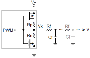
In one example, the counters can be configured for N = 16. The PWMs can have duty cycles of 1/16, 2/16, 3/16, all the way up to 15/16. The remaining state will be either 0/16 or 16/16. The two PWM outputs are connected by the series combination of two resistances in a ratio of 1:16. At the junction of these two resistors, there are 24×24 = 28 possible average values, just as there would be with a single PWM presenting 28 different states. The simplest way to effect AC attenuation is to connect a capacitor between that junction and ground (Figure 1 is an example of the complete circuit.)

Figure 1 A complete circuit representing the simplest method to effect AC attenuation where a capacitor is connected between the junction of the two resistors at the PWM outputs and ground.
But both this and the traditional PWM can benefit from a more complex network with larger numbers of resistors and capacitors, and optionally even an op amp to buffer the results. The op amp can also enable the implementation of filters containing complex pole pairs instead of being limited to real poles, the real poles being the only ones otherwise obtainable. The former type more effectively minimizes the product of filter settling time and the magnitude of residual AC energy. (An example of such has been presented in an earlier Design Idea.)
I used an ATmega16 microcontroller to implement the Figure 1 circuit. F was set to 1MHz, although much higher clock frequencies were available. PWM 1 and PWM 2 were configured to operate in two different modes: as the two four-bit units described before with outputs of independent values, and as eight-bit units with identical outputs. This maintained the same R-C filter time constant for both modes of operation. The repetitive sequences of the OCRs for each mode are listed in Table 1.

Table 1 OCR values used by the four-bit and eight-bit PWM modes for generating the Figure 2 waveform.
Figure 2 shows a scope capture of one of the two modes; screen shots of the two modes are indistinguishable from one another, as are their approximately 18 mV resolutions. (It was necessary to connect an additional resistor, not shown, between the R1-R2-C1 junction and a negative DC voltage. Without disturbing the R1-R2 ratio, this moved the waveform’s voltage close to ground so that the scope could display it with high resolution.)

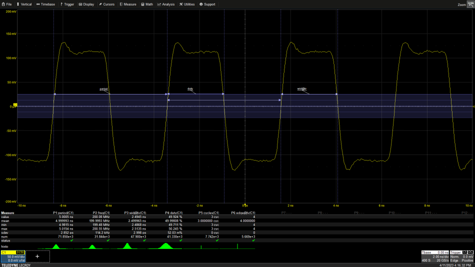
Figure 2 Waveform generated by programing the OCRs as listed in Table 1 for both the four-bit and eight-bit PWM modes. The two modes’ results appear identical since the scope averages out AC energy at the 200 ms/div sweep rate.
Each of the two four-bit PWMs has frequencies of F/16 = 62.5 kHz; the frequencies of the eight-bit ones are F/256 = 3.90625 kHz. The code changed the OCR registers approximately every 100 ms. At the Figure 2 sweep rate, the scope filtered out the PWM AC signals, replacing them with average values. At faster sweep rates in subsequent figures, the scope revealed their peak-to-peak amplitudes. Figure 3 shows 120 mV for the eight-bit PWMs, while Figure 4 reveals a mere 7.5mV for the four-bit ones.

Figure 3 The AC energy across the capacitor in the Figure 1 circuit for the eight-bit PWM.

Figure 4 The AC energy across the capacitor in the Figure 1 circuit for the four-bit PWM. The period and amplitude are 16 times smaller for the four-bit than for the eight-bit PWM.
With a step resolutions of 18 mV for both modes, the four-bit peak-peak noise is near optimal at just less than half a step; any more AC signal attenuation would needlessly increase the 1 ms half-step settling time. At 120 mV (6.7 steps) peak-to-peak at 1/16 the frequency, the eight-bit PWM implementation is pretty much unusable. The capacitor value would have to be increased to 15µF with an associated 15x increase in settling time to meet the energy attenuation performance of the dual four-bit PWM approach.
The approach employed in this example is a powerful one. With a pair of eight-bit PWMs interconnected with 0.1% resistors having a ratio of 256:1, a (dual eight-bit) 16-bit PWM can have an AC output that would be 256 times easier to filter than a classical 16-bit unit. PWM resolutions of less than N = 216 or 28 levels are also possible with concomitant reductions of PWM periods and associated simplifications of filtering requirements. There are even microcontrollers with three or four PWMs whose outputs might be added together with a suitable resistor network.
Christopher Paul has worked in various engineering positions in the communications industry for over 40 years.
Related Content
Optimizing a simple analog filter for any PWMA Sallen-Key low-pass filter design toolkitBuilding optimal sensitivity third order low pass filters with a single op ampDesigning second order Sallen-Key low pass filters with minimal sensitivity to component tolerancesReferences
https://www.gaussianwaves.com/2018/09/maximum-length-sequences-m-sequences/https://ww1.microchip.com/downloads/en/DeviceDoc/SAM_D21_DA1_Family_DataSheet_DS40001882F.pdf, pp.633-634Easing filtering for PWMs由Voice of the EngineerAnalogColumn releasethank you for your recognition of Voice of the Engineer and for our original works As well as the favor of the article, you are very welcome to share it on your personal website or circle of friends, but please indicate the source of the article when reprinting it.“Easing filtering for PWMs”