Simple XOR logic elements on transistors
- Analog
- 2023-09-23 21:19:49
Logic elements “Exclusive OR” are widely used in a variety of digital devices. However, in some cases, for example, when using increased operating voltages, the use of standard chips is impossible. This problem can be solved by using discrete elements.
Wow the engineering world with your unique design: Design Ideas Submission Guide
If the standard AND or OR logic elements are easily replaced by diode-resistive circuits, then the situation is much more complicated for XOR elements. It is worth noting that 3XOR logic gates are not manufactured by the industry. It will be shown below how 2XOR and 3XOR elements can be synthesized from a set of standard discrete elements.
Figure 1 shows how a 2XOR element can be synthesized from a combination of 2OR and 2AND logic elements and a VT1 transistor. In turn, the elements 2OR and 2AND can be replaced with their counterparts from discrete elements. For example, diodes D1 and D2, as well as resistors R1 and Rload (Rload >> R1) serve as the equivalent of a logic element 2OR, Figure 1. Diodes D3 and D4, as well as resistor R2, are the equivalent of a 2AND logic element.


Figure 1 The XOR logic element and its analog using discrete elements.
The second variant of the 2XOR element is shown in Figure 2. Transistors Q1 and Q2, as well as resistor R2, serve as the 2AND element.

Figure 2 The logic element XOR composed of discrete elements.
The following variants of analogs of the 2XOR logic element are made on field-effect (Figure 3) and bipolar (Figure 4) transistors.

Figure 3 The logic element 2XOR on field-effect transistors.
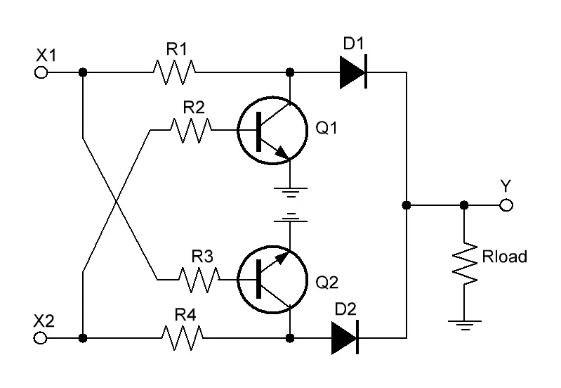
Figure 4 The logic element 2XOR on bipolar transistors.
Obviously, if “Log. 0” levels are present at the inputs X1 and X2, “Log. 0” will also be observed at the output of the element.
When a signal of the “Log. 1” level is applied to one of its inputs, for example, X1, and a signal of the “Log. 0” level is applied to the input X2, this signal will pass through the resistor R1 and the diode D1 to the output Y of the device. Of course, the output voltage will be slightly lower than the input, which in most cases is not critical for the operation of digital equipment, especially working in the area of elevated voltages.
A similar situation will occur when a “Log. 1” level signal is applied to the input X2, and a “Log. 0” level signal is applied to the input X1.
If the signals are “Log. 1” are applied to both inputs of the device, both transistors Q1 and Q2 will open and prohibit the passage of input signals to the output of the device.
Analogs of the 3XOR logic element, Figure 5 and Figure 6, are much more complicated than the previous ones, but it is worth considering that due to the increased complexity of execution or for other reasons, such elements in the form of microcircuits are not produced. Table 1 (truth table) characterizes the output signal level of a 3XOR logic element depending on the set of input signals.

Figure 5 The logic element 3XOR on bipolar transistors.

Figure 6 The logic element 3XOR on field-effect transistors.

Table 1 The truth table of the 3XOR logic element.
Michael A. Shustov is a doctor of technical sciences, candidate of chemical sciences and the author of over 750 printed works in the field of electronics, chemistry, physics, geology, medicine, and history.
Related Content
Universal purpose optoelectronic logic element with input optical switching of AND/NAND, OR/NOR and XOR/XNOR functionsUniversal purpose optoelectronic logic elementsUniversal logic element on one transistor and its applicationsImproved comparators distinguish between A = B = 0 and A = B = 1 states to enable better designsBinary elements of fractional logicSimple XOR logic elements on transistors由Voice of the EngineerAnalogColumn releasethank you for your recognition of Voice of the Engineer and for our original works As well as the favor of the article, you are very welcome to share it on your personal website or circle of friends, but please indicate the source of the article when reprinting it.“Simple XOR logic elements on transistors”