Power Tips #118: Using interleaved ground planes to improve noise filtering from isolated power supplies
- Analog
- 2023-09-23 21:19:45
Historically, automotive electronics have been powered off the same 12-V lead-acid battery used to start the vehicle. Even with surges as high as 42 V, which could occur if the generator were running and the battery cable was disconnected, voltages stay in the safety extra-low voltage (SELV) range below 60 VDC. Thus, it was not necessary to worry about the spacing of conducting PCB traces to avoid electrical shock hazards in automotive circuitry.
Because electric vehicle (EV) motors need higher voltages (400 V or 800 V) to operate, shock hazards are now a concern in automotive applications. The same stringent spacings that apply to the boundary between circuitry connected to the AC mains and SELV circuits powered off of utility power, now apply to the boundary between the circuitry connected to the high-voltage batteries in EVs and the SELV circuits running off the 12-V system, such as infotainment and body electronics (mainly lighting).
Failing CISPR 25
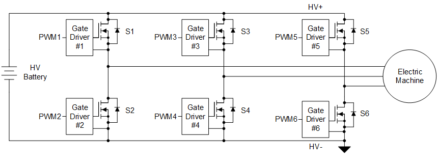
Many of the bias supplies needed to drive high-power semiconductor switches in traction inverters operating off high-voltage EV batteries are powered off the low-voltage 12-V system. The problem is that these isolated power supplies pump a lot of common-mode noise back into the 12-V car battery lines, causing them to fail the automotive Comité International Spécial des Perturbations Radioélectriques (CISPR) 25 conducted emissions limits, which extend to 108 MHz. This noise is largely driven by the main switching waveform capacitively coupling between the primary and secondary windings of the bias supply’s isolation transformer. Bypass capacitors with high surge voltage ratings (Y-capacitors) between primary ground and secondary ground create a small loop to largely contain this common-mode noise, and common-mode filtering on the battery lines further reduce this noise to allow passing of CISPR 25 limits.


Spacing requirements for automotive circuitry
For reinforced spacing between high-voltage EV batteries and the low-voltage 12-V battery system used in most traditional automotive circuitry, a common target is 8 mm of spacing. This will cover 400 VRMS, pollution degree 2 and material group III; or 800 VRMS, same pollution degree 2, but material group I. For more details regarding spacing requirements, see the International Electrotechnical Commission (IEC) 60664-1 standard, “Insulation coordination for equipment within low-voltage supply systems—Part 1: Principles, requirements and tests”.
Meeting creepage and clearance requirements in multi-layer PCBs
IEC’s stringent spacing requirements are driven by a high-voltage breakdown on surfaces exposed to contaminated air (creepage) and a breakdown or arcing of the air itself (clearance). Within components that bridge the primary-secondary barrier such as transformers or ICs—and likewise the inner layers of multilayer PCBs where there is no air or moisture exposure—spacing requirements are much less, as long as the barrier can withstand a several-kilovolt high-potential test. A common test level for ICs used in reinforced barrier applications is 5 kV, which allows PCBs with four or more layers to have interleaved primary and secondary grounds on the inner layers. There are spacing requirements within inner layers, but they are significantly reduced from the requirements for air-exposed layers. For some applications, a 1-mm spacing would be sufficient for 800-V battery systems.
Demo with an isolated DC/DC converter
We built two boards to demonstrate emissions performance versus CISPR 25 Class 5 limits of our UCC12051-Q1 isolated DC/DC converter. This converter was designed for 5-V input and 5-V output loaded at 100 mA with a typical battery-line electromagnetic interference filter. One board (not released) had 8-mm spacing between the primary and secondary on all four layers, and one board (the Isolated 5-V Bias Supply for Automotive CISPR 25, Class 5 Emissions, Reference Design) allowed the interleaving of primary and secondary grounds in the two inner layers, with spacing between primary and secondary grounds at 1 mm. The additional effective capacitance from primary ground to secondary ground was an estimated 11 pF. The isolated converter inside the UCC12051-Q1 switched at 8 MHz to ensure that its first frequency of CISPR 25 concern would be its fourth harmonic at 32 MHz.
Figure 1 is snippet from the isolated 5-V reference design schematic showing an IC isolated converter with capacitors from primary ground to secondary ground to contain high-frequency noise generated by the converter’s isolation transformer. The unreleased board is the same as the isolated 5-V reference design, except for the lack of PCB layer interleaving.

Figure 1 Primary and secondary interface of the DC/DC converter in the isolated 5-V reference design showing added bypass capacitors C100 and C101 and interleaving inner-layer capacitance. Source: Texas Instruments
Given the need for redundancy for safety and the need to maintain overall spacing from primary to secondary, we placed two Y-capacitors (C100 and C101) in series to bridge the primary and secondary grounds. Hence, the effective capacitance is one-half the value of each capacitor. Some cases will need three capacitors in series—330 pF capacitors—to maintain the necessary spacing.
In Figure 2, the image on the left is the not released board with 8-mm spacing for all layers; the image on the right is the isolated 5-V reference design with the top and bottom layers having 8-mm spacing and the inner layers having only 1-mm spacing, allowing them to have overlapping primary and secondary ground planes.

Figure 2: 8-mm spacing on all layers (left) versus 8-mm spacing on only the top and bottom layers (right): top layer—red; layer 2 is dark green; layer 3—light blue; layer 4—tan; overlap of layers 2 and 3—light green; no copper on any layer—black. Source: Texas Instruments
Radiated emissions versus CISPR 25
With the isolated 5-V reference design, we expected that this interleaving, with its added 11 pF of capacitance between primary and secondary grounds, would only help radiated emissions above 200 MHz. And indeed, the interleaving layers allowed radiated emissions to pass CISPR 25 Class 5 for all frequencies above 200 MHz, even without bypass capacitors C100 and C101 (Figure 3). Without the interleaving layers, we needed additional Y-capacitors between primary and secondary grounds to pass in the same frequency range. See the test report for the emissions test setups.

Figure 3 Radiated emissions versus CISPR 25 Class 5 above 200 MHz without any additional Y capacitors. This specific scan is not in the isolated 5-V reference design test report. The board passed limits with greater than 10 dB of margin. Source: Texas Instruments
The surprise was that filtering (C101 and C102) for the 30- to 108-MHz range, with its stringent conducted emissions limits, was significantly enhanced. With 110 pF of effective additional capacitance between primary ground and secondary ground, the interleaving improved the conducted noise reduction throughout the entire 30- to 108-MHz range by about 4 to 8 dB. Over this frequency range, the interleaving converted a failure by 4 dB to a pass with 4 dB of margin.
Conducted emissions versus CISPR 25
Figure 4 and Figure 5 show the conducted emissions scans of these two boards, with the only difference being the inner-layer interleaving. Both scans were on the same line impedance stabilization network (LISN), with the same common-mode battery line filtering and the same loading of 100 mA off the 5-V output.

Figure 4 Isolated 5-V reference design (with interleaving layers) conducted emissions versus CISPR 25 Class 5, 30 to 108 MHz: passed with 4.5 dB of margin, with the worst case being a “CISPR average” detection at 82 MHz. Source: Texas Instruments

Figure 5 Unreleased board (no interleaving layers) conducted emissions versus CISPR 25 Class 5, 30 to 108 MHz: failed by 3.8 dB of margin, with the worst case being a CISPR average detection at 32 MHz. Source: Texas Instruments
The interleaving layers with the estimated 11 pF of capacitance contributed far more to the filtering than adding 11 pF to the effective 110 pF of capacitance of the Y-capacitors, which would improve filtering by about 1 dB. The inner-layer ground planes reduce the effective inductance of the bridging Y-capacitors and allow them to better shunt these high-frequency harmonics.
This filtering improvement adds to the benefits of close-in ground planes, improving the performance of capacitor filtering whether the goal is to limit output noise, control emissions in non-isolated applications, or reduce stresses and failures on semiconductors.

Josh Mandelcornhas been at Texas Instrument’sPowerDesign Services team for almost two decades focused on designingpower solutions for automotive and communications applications. He has designed high-current multiphase converters topowercore and memory rails of processors handling large rapid load changes with stringent voltage under / overshoot requirements. He previously designed off-line AC to DC converters in the 250W to 2 kW range with a focus on emissions compliance. He is listed as either an author or co-author on 17 US patents related topowerconversion.
Related Content
Power Tips #117: Measure your LLC resonant tank before testing at full operating conditionsPower tips #116: How to reduce THD of a PFCPower Tips #115: How GaN switch integration enables low THD and high efficiency in PFCPower Tips #114: A potential firmware mistake may lead to control instabilityStop EMI from spreading in an EV designA new EMI threat?Additional resources
Use the PCB creepage calculator for reinforced isolation double results.Check out more from Texas Instruments:“How to Meet the Higher Isolation Creepage & Clearance Needs in Automotive Applications.”“Power Tips: The Ground Plane – A Critical Element in Noise Management of Switching Regulators.”“Power-Conversion Techniques for Complying with Automotive Emissions Requirements.”“Reduce Buck-Converter EMI and Voltage Stress by Minimizing Inductive Parasitics.”Relevant standards
IEC 60664-1 Insulation Coordination for Equipment Within Low-Voltage Supply Systems – Part 1: Principles, Requirements and TestsIEC 61800-5-1 Adjustable Speed Electrical Power Drive Systems – Part 5-1: Safety Requirements – Electrical, Thermal and EnergyInstitute for Interconnecting and Packaging Electronic Circuits (IPC) 2221B Generic Standard on Printed Board DesignCISPR 25 Ed. 5.0 b 2021 Vehicles, Boats and Internal Combustion Engines – Radio Disturbance Characteristics – Limits and Methods of Measurement for the Protection of On-Board ReceiversPower Tips #118: Using interleaved ground planes to improve noise filtering from isolated power supplies由Voice of the EngineerAnalogColumn releasethank you for your recognition of Voice of the Engineer and for our original works As well as the favor of the article, you are very welcome to share it on your personal website or circle of friends, but please indicate the source of the article when reprinting it.“Power Tips #118: Using interleaved ground planes to improve noise filtering from isolated power supplies”