The electronic analogue of the push
- Consumer
- 2023-09-23 22:51:37
The electronic analogue of the push-button switcher allows you to selectively turn on one or another load from several possible ones, while simultaneously disabling the previously turned on load of another control channel. Unlike a mechanical switcher, it is possible to turn off the previously selected load by pressing the control button again.
Wow the engineering world with your unique design: Design Ideas Submission Guide
The electronic device described in the article can replace a multi-button switcher. The electronic analogue of the push–button switcher uses bistable elements (Figure 1), which are turned on by applying a high-level voltage to the input of the element and turned off by applying a low level.
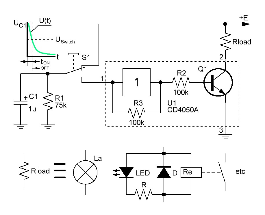


To turn on and off the bistable element, the discharge of the capacitor C1 to the resistance R1 is used. As shown in Figure 1, during the initial moment of the discharge process, a short press on the control button S1, turns on the bistable element and the load resistance. A longer press on the control button S1, turns off the load.
The S1 button press duration that is sufficient to turn off the load is defined as toff[sec] ~ 2R1[Ohm]C1[Farad] and, at the nominal values indicated in the diagram, is 0.15 seconds.
In order to be able to control the switching of one of several loads using several control buttons, a dependent load switching scheme is used. Figure 2 shows a diagram of a three-button analog of a mechanical load switcher.

Figure 2 Electrical diagram of a three-button electronic analog of a mechanical load switcher.
This electronic analogue of the push–button switcher allows a short press on one of the control buttons S1–S3 to turn on the selected load Rload1-Rload 3, simultaneously disabling other loads. Unlike mechanical switches, pressing the control button for a longer time will ensure that the previously selected load is turned off.
The circuit in Figure 2 uses 6 diodes D1–D6. In general, a circuit switching with n loads will require n bistable elements (See Figure 1) and n(n–1) diodes. So, for n=1, diodes are not needed; for n=2, it is necessary to use 2 diodes; for n=3, 6 diodes are needed; for n=4, 12 diodes are required, etc.
If diodes D1–D6 are removed from the device in Figure 2, the electronic analogue of the mechanical switcher will be able to turn on and off each of the loads Rload1–Rload3 independently of each other by pressing the corresponding button S1–S3.
Related Content
Push-button bathroom fan switch design supports timed operationLatching power switch uses momentary pushbuttonMulti-position switch controlled by amplitudeLoad switch-timer with multi-point control over two wiresThe electronic analogue of the push由Voice of the EngineerConsumerColumn releasethank you for your recognition of Voice of the Engineer and for our original works As well as the favor of the article, you are very welcome to share it on your personal website or circle of friends, but please indicate the source of the article when reprinting it.“The electronic analogue of the push”