Comparing conducted emissions from LED lamps
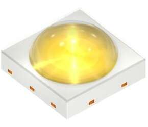
- LEDS
- 2023-09-23 23:13:33
Radio frequency interference (RFI) to frequencies in the AM and shortwave broadcast bands has been on the increase in the last two decades, due primarily to switch-mode power supplies being used for environmental reasons. This affects reception not only in these bands, but military and amateur radio communications in the 1.8 to 30 MHz frequency bands as well. These emission sources produce interference that can affect radio reception from 100s of feet to a mile away, or more.
This interference is largely due to the myriad of “wall wart” and “fat snake” (detachable) power supplies, as well as switching power supplies in household appliances, solar panels, power tools, and the dozens of internet-connected devices now in our homes. It is also due to the CFL and LED lamps commonly in use now that we’ve transitioned away from incandescent lighting.
LED lighting interference will be the focus of this article. A few years ago, I wrote about the unfiltered lighting ballasts (switching power supplies) used for illegal marijuana grows occurring in Oakland, California and other urban areas of the country. These were causing RFI between 1 and 2 miles away.
When LED lighting first became commercially available around 2010, I had purchased several samples to test in the Agilent Technologies (at the time) EMC chamber. While I never published the results, they were not encouraging. Recently, I purchased another smaller sample to compare the results to determine if there had been any improvement over the last decade. With one surprising exception, I was disappointed to observe little improvement in emissions level. We’ll be measuring conducted emissions, but because these LED lamps are typically connected to largely unshielded building wiring, we can get extreme radiated emissions in these frequencies as well.


Measuring conducted emissions
I used the conventional conducted emissions test setup in Figure 1. For these tests, I used a model TBLC08 line impedance stabilization network (LISN) from Tekbox and a model SSA3032X spectrum analyzer from Siglent. A solar model 7032-1 isolation transformer was used to power the LISN. Aluminum foil was spread out on the table, which provided a path for common mode currents back to the LISN and the LISN was bonded to this foil ground plane. A photo of the set up is shown in Figure 2.
Note that all these measurements were made using peak detection, so would indicate higher than quasi-peak measurements shown in the limits below. I believe peak emissions is valid for the typical AM and SSB reception by general public and military users in these bands. Both line and neutral plots were recorded from 150 kHz to 30 MHz. Ideally, both line and neutral should measure the same. The measurement data was split between LED bulbs from 2010 and those purchased in 2021. All bulbs purchased were 60 watt equivalent.


Limits for luminaires
The limits for luminaires, such as LED lamps, are dictated by IEC/EN 55015:2019. The frequency range for conducted emissions ranges from 9 kHz to 30 MHz and the quasi-peak (QP) limits are described in the table of Figure 3. Schaffner provided a more clear plot of these QP limits in Figure 4. Note that the test results for ALL these bulbs met the limits of IEC/EN 55015, however, all but the last example would produce some level of RFI to sensitive radio receivers in the 150 kHz to 30 MHz (and higher) bands.


Results for 2010 LED bulbs
Back in 2010, LED bulbs were quite new and relatively expensive. While I’d purchased and tested several at that time, I decided to retest, so I could directly compare with a couple newer ones purchased in 2021. There was a wide range in emissions as you can see in Figures 5-7.


Results for 2021 LED bulbs
I was able to purchase a couple newer LED bulbs to compare with those purchased a decade ago. There was less of a range noted in these two bulbs (Figure 8 and 9). Figure 9 was a real surprise, though.


All these LED bulbs, except the last, would have produced some level of RFI in sensitive receivers in the bands 150 kHz to 30 MHz, and some much worse than others. While FM reception would not be affected much, a building full of LED lighting would be quite detrimental to sensitive AM and SSB radio installations using these bands. This would also likely affect AM aircraft communications in the bands from 108 to 136 MHz. My recommendation would be to stick with well-known manufacturers or at least measure the conducted and radiated emissions first prior to committing to lighting vendors for large installations with known sensitive communications.
—Kenneth Wyatt is president and principal consultant of Wyatt Technical Services.
References
Wyatt, Workbench Troubleshooting EMC Emissions (Volume 2)Electromagnetic Compatibility of Lighting Equipment, SchaffnerStandards for LED drivers, LED modules and LED luminaires, OsramRelated articles:
Ensure EMC compliance in automotive LED designReview: Tekbox LISNsEMI emissions testing: peak, quasi-peak, and average measurementsConducted emissions testingHow cops are finding “grow ops” with AM radiosReduce EMI by driving high-power LEDsRFI: keeping noise out of your designsComparing conducted emissions from LED lamps由Voice of the EngineerLEDSColumn releasethank you for your recognition of Voice of the Engineer and for our original works As well as the favor of the article, you are very welcome to share it on your personal website or circle of friends, but please indicate the source of the article when reprinting it.“Comparing conducted emissions from LED lamps”