Power Tips #110: How parasitics create an unexpected EMI filter resonance
- Automotive
- 2023-09-23 21:29:56
Electromagnetic interference (EMI) has a reputation for being one the most difficult aspects in power-supply designs. I think that this reputation comes, in large part, from the fact that most EMI-related challenges are not things that can be solved by looking at the schematic. This can be frustrating, since the schematic serves as the central place where the engineer goes to understand what the circuit does. Sure, you know that there are relevant functions in the design that are not in the schematic—things like code.
You also know that the schematic doesn’t represent things like printed wiring board parasitics. However, in EMI, parasitics like these can have dominating effects in your ability to meet the requirements, forcing you to have the necessary experience to recognize what types of parasitics can positively or negatively impact the EMI spectrum. This Power Tip article will explore how these types of parasitics can create an unexpected EMI filter resonance in a gallium nitride (GaN)-based onboard charger (OBC) for an electric vehicle (EV).
Figure 1 shows a high-level system representation of the OBC. Its primary function is grid-to-vehicle voltage and current battery charging. A secondary function is vehicle-to-grid power flow so that the EV can supplement renewable energy sources that might have a fluctuating peak capacity.
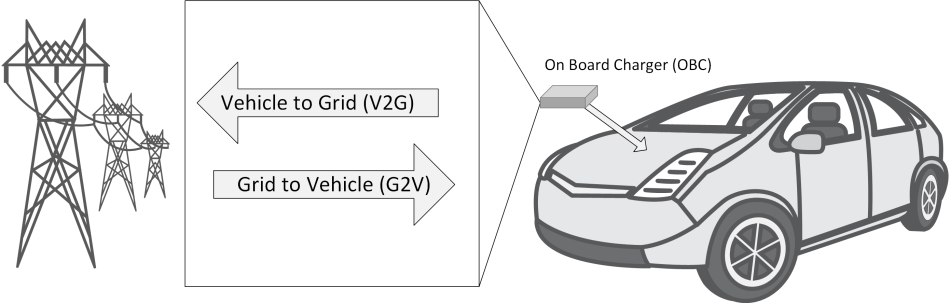


Figure 1 The schematic shows a high-level system representation of the onboard charger (OBC). Source: IEEE
Now, let’s turn our attention to the EMI considerations inside the OBC.
Onboard charger’s EMI review
EMI includes differential-mode (DM) and common-mode (CM) noise. For an OBC system, DM noise is mainly generated by the input current of the power factor correction (PFC), while CM noise can result from both the PFC and the conductor-inductor-inductor-inductor-capacitor (CLLLC). Figure 2 shows the cooling solution (cold plate) for the OBC in the lower right corner of the schematic. The cold plate is critical in preventing the components from overheating; however, its presence introduces parasitic capacitance that affects the EMI.

Figure 2 Parasitic effects causing EMI are shown in the lower right corner of the schematic. Source: Texas Instruments
As shown in Figure 2, there are parasitic capacitances between the switching nodes to the cold plate, between the primary and secondary grounds to the cold plate, and between the primary and secondary winding of the CLLLC transformer. Those parasitic capacitances can generate or affect CM noise-current levels in the system.
With estimated parasitic capacitances, simulations show that in the worst case, the bare DM noise with only the 2.2-µF input capacitor (CX1) is about 110 dBµV. Likewise, the bare CM noise without any CM filter is about 115 dBµV at about 350 kHz. Designing a two-stage EMI filter helps attenuate EMI noise below the Comité International Spécial des Perturbations Radioélectriques (CISPR) 32 standard.
The common-mode impedance of LCM1 and LCM2 at 350 kHz is about 3 kΩ. Their leakage inductances are about 6.4 µH, which are used for DM noise attenuation. CX1 and CX2 are 2.2-µF film capacitors for DM noise attenuation, and CY1, CY2, CY3 and CY4 are 4.7-nF ceramic capacitors for CM noise attenuation.
Ideally, with the designed filter, both the bare CM noise and bare DM noise should be attenuated by more than 65 dBµV, and the EMI noise should meet the CISPR 32 standard. There are still some practical challenges to address, however.
EMI filter resonance
EMI filters are filled with resonances by design. In fact, it is these resonances that enable the filter to attenuate noise and enable a system to pass the EMI standard. Figure 3 shows a typical attenuation curve for an EMI filter. Notice that at frequencies above 100 kHz, the filter does a nice job of reducing amplitude. There are some resonances below 100 kHz, however, that could be quite problematic if they exist on top of a switching frequency.

Figure 3 This is how typical EMI filter attenuation looks like for an onboard charger. Source: Texas Instruments
Obviously, no one would intentionally place a resonance at the switching frequency, but interconnect impedances, component parasitics or both can sometimes push the system to operate in an unintentional way.
Figure 4 shows a slightly modified EMI filter compared to Figure 2. The differences are in the components in red. LP1 and LP2 represent the parasitic inductance of the interconnect between the EMI filter and the PFC input. The presence of LP1 and LP2 required some local capacitance for the PFC current to flow through. Therefore, moving CX1 to the input of the PFC and adding CX0 increased the attenuation of the filter. The four elements in red combine together to create a resonance at 240 kHz. In this design, 240 kHz is the conversion-combined switching frequency of the two-phase PFC. This resonance is going to amplify the switching current and subsequently make the EMI worse at this frequency.

Figure 4 The EMI filter is shown with a resonance at the switching frequency. Source: Texas Instruments
Figure 5 shows the time-domain waveforms of the AC line current flowing through LP1 in magenta, along with the AC input voltage in blue. Notice that the current has a significant 240-kHz sine wave with a 28-A peak-to-peak amplitude. This sine wave is the direct result of the triangular PFC current flowing through the unintended amplifier created by the red components in Figure 4.

Figure 5 The time-domain waveforms of the AC line current are shown flowing through LP1 in magenta. Source: Texas Instruments
Damping a resonance like this can be challenging, since the necessary damper will typically require an inductor or capacitor larger than those used in the circuit. Another possible solution might be to lower the inductance of the interconnect so that the resonance is no longer on top of the switching frequency. In theory this sounds good, but practically speaking, that interconnect is there for a reason; so, making it smaller isn’t really viable.
Another option is to consider the necessity of retaining both CX0 and CX1. You can’t remove CX1 since the PFC requires some local input capacitance for the high-frequency current. However, CX0 is there to increase the capacitance, with the intent of increasing the attenuation. Removing CX0 improved the EMI by approximately 6 dBµV. The amplitude is reduced by 50% and a large percentage of the require attenuation (65 dBµV) needed to pass the standard. That’s a pretty good deal.
Two design takeaways
The takeaway here is twofold. The first is the original premise: the schematic doesn’t tell the whole story for EMI. In this case, there was an unintended resonance caused by interconnect inductance that amplified the switching frequency noise. Recognizing the root cause of the problem is always the most critical step in debugging.
The second takeaway is that sometimes less of a normally good thing (filter capacitors) is better. You can usually address EMI issues by adding components, but in this case, the presence of a component makes the issue worse. Therefore, by removing CX1, we were able to reduce the size of the filter, lower the system cost, and improve the EMI.
Brent McDonald is a system engineer in the Power Supply Design Services team at Texas Instruments.
Related Content
Reduce EMI by varying power supply frequencyReduce EMI by sweeping a power supply’s frequencyThe 13-Step EMI Mitigation Program for Switching Power SuppliesProper layout and component selection control power-supply EMINovel Metal Core Design Enables Smaller Size, Higher Currents in EMI FiltersPower Tips #110: How parasitics create an unexpected EMI filter resonance由Voice of the EngineerAutomotiveColumn releasethank you for your recognition of Voice of the Engineer and for our original works As well as the favor of the article, you are very welcome to share it on your personal website or circle of friends, but please indicate the source of the article when reprinting it.“Power Tips #110: How parasitics create an unexpected EMI filter resonance”