There’s more to driver monitoring system than pretty pictures
- Automotive
- 2023-09-23 21:29:46
With people at the wheel ever more susceptible to distractions, drowsiness and impairment, driver monitoring systems (DMS) are considered key in accident prevention. But are we overdesigning the sensors at the heart of these systems? Simulations using a new sensor modeling tool and a deep neural network (DNN) indicate it is plausible that we are—by a lot. This means the automotive sensor industry has an opportunity to substantially decrease DMS power and cost without sacrificing critical performance.
Time is of the essence. As of 2024, all new vehicles sold within the European Union must be equipped with a DMS. At the same time, other functions, such as occupancy monitoring and videoconferencing, must be integrated in the same camera system.
DMS design starts at the sensor level. The current sensor crop is designed with full functionality, so they can take very “pretty pictures” under a wide range of operating and lighting conditions. But do we need pretty pictures? Or are we doing the engineering equivalent of putting out a match with a firehose?
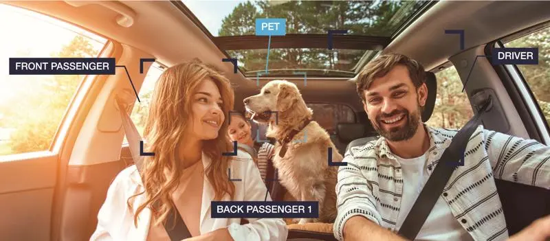
DMS must detect facial characteristics, such as the mouth, nose, and eyes to determine the alertness of the driver (Figure 1). Could we simplify the design of sensors so that they cleanly capture the pertinent information, even under difficult environmental conditions, and optimize the power-performance-area (PPA) budget for those features while also keeping the cost down?


Figure 1 DMS must detect facial characteristics such as the mouth, nose, and eyes to determine the alertness of the driver. Source: OmniVision
At OmniVision, we developed a simulation tool for internal use to look at ways we could optimize sensor PPA for other applications. Then, we shared it with some of our customers to see if it could also be used for DMS sensors. Rudimentary tests indicated there is a substantial potential for optimization.
When good enough is enough
We want to use our tool to help determine the most applicable DMS specifications and come up with the most simplified image sensor we can make that will still work. The most simplified image sensor? Yes, indeed. We do not want to overdesign, which increases cost and energy consumption. We want to make the right product for DMS: that starts with knowing what is “just good enough” and honing it from there.
DMS systems subtly light the driver’s face using 940 nm infrared (IR) illumination in short, high-power pulses. This requires global shutter (GS) imagers rather than the rolling shutters you’d find in your cell phone. However, the template for DMS GS specifications still largely targets the objectives of taking “pretty pictures”.
While DMS systems can certainly operate with overdesigned sensors, as pixels shrink and as cost and performance requirements evolve, or new functions need to be added, they call for more custom, application-specific solutions.
Critical specifications—or not?
In sensors for DMS, the critical GS specifications are noise performance, shutter efficiency, analog/digital conversion (ADC), high dynamic range and dark current. Our experience and user feedback suggested that while these specifications are important, they are not the same for DMS as for the industrial vision applications from which they originated.
For example, low light is not a major issue for DMS. It’s more important to design for immunity to sunlight as it can obscure the 940-nm IR pulses. Additionally, ADC resolution is not as critical for DMS as it is for industrial vision applications. Understanding different DMS requirements provides us with opportunities for optimization.
Why the worst?
Today the flow to derive specifications for sensor optimization is to take pictures and optimize the algorithms, as shown in the top line of Figure 2. A camera grabs images of a scene and the scene is processed. Next, key performance indicators (KPIs) are calculated for adaptive optical (AO) accuracy of gaze direction, and the information is fed back to the algorithm development.

Figure 2 Here is a view of deriving sensor specifications implemented through closed-loop simulation. Source: OmniVision
One way to explore overdesign is to build a sensor with worse sensor performance and see if it’s good enough. But that’s obviously not trivial. We would instead like to evolve to a state where we can introduce new sensor characteristics without the need for sensor silicon.
Our proposal is to add simulation in a closed loop. We will still be taking the same images with the same camera. But now through simulations, we will test our sensors by making those images worse.
OmniVision’s sensor simulation tool, while developed for a broader use, may serve this purpose. The tool covers all aspects from rudimentary scene generation through image processing. After scene generation, an optical image is created on the sensor surface, the electro-optical performance is modeled, and image processing gets applied on the output images.
The electro-optical model can also be used to intercept and postprocess captured images. This lets us degrade the image quality through simulation. By emulating the color filter array (CFA) and quantum efficiency (QE) performance, and introducing any pixel architecture and performance, we can translate the optical signal to an electrical signal. The electrical signal can then be processed at any appropriate gain while introducing response and dark level non-uniformity. Here, we can introduce temporal noise, dark current and flicker noise as well as pixel crosstalk.
In the broad sense, we can use the simulation tool during the development of new pixel concepts. It makes it possible for us to perform “what if” analysis on any kind of pixel architecture or performance characteristics and evaluate its influence on the system performance.
Trying it out
We put our sensor simulation tool to the test in an experiment using an eye tracking neural network inspired by a model of the human eye. The goal was to ascertain the accuracy of detection for gaze direction. While the conditions were simplified compared to an actual DMS use case, we believe the high-level conclusions still apply. The proposed model extracts typical features such as the pupil from an image of an eye to create a segmentation map, so the input of each convolutional layer is only dependent on the output from the previous layer and removal of the concatenation steps to reduce memory requirements. These simplifications make the network viable for a low-cost implementation.
As part of work presented in the reference publication, the authors had already trained a neural network. Using stock images of human eyes (Figure 3, above), we used this trained neural network to obtain a “ground truth” for further use in our analysis.


Figure 3 We ran two cases with 7 and 10 DN on an 8-bit scale, which is well beyond what any sensor would really need to do, and we introduced RN, Hnoise and VFPN and all combination. Source: OmniVision
Next, we used our tool to add random sensor noise at different noise levels to the dataset (Figure 3, below). These degraded images were run, once again, through the author-trained network and by comparing these to our ground truth, we could derive the error that was introduced because of the noise. The performance, unsurprisingly, was not good (Figure 4). The accuracy of gaze detection was worse than 5% and often segmentation completely failed. A misshapen eye segmentation produces errors, and if there is no pupil at all in the segmentation, the calculation fails; the error in these cases was clipped to 20%.

Figure 4 Error percentage of gaze direction is more than 5% and many cases fail pupil detection during segmentation (20% error). Source: OmniVision
Since adding noise made the network fail, we decided to retrain the network. We again added noise to images, but then we retrained the neural network on the noisy images created using our sensor simulation tool, essentially teaching the network how to deal with noisy images.
In the next step, we again added noise to images and ran them through the newly retrained network. This time the error was generally < 2% failure and segmentation failures were very rare (Figure 5). Retraining with noise ensured robust segmentation, and it showed that we got an accurate pupil position. From there we can break down what the performance would look like for the various types of noise.

Figure 5 When training on noise, error of gaze detection is greatly improved (<2%) and with hardly any segmentation failures. Source: OmniVision
The system demonstrated here is by no means a professional DMS. The images we used are not representative for the challenges in a DMS use case. However, this experiment with a very rudimentary neural network showed that eye gaze detection fundamentally has a low sensitivity to noise. While a DNN may very well fail on noisy images, training the network for noise deals with the noise quite effectively.
It takes an ecosystem
Our simple example suggests it is plausible that today’s sensors for DMS are overdesigned. However, we need collaboration across the automotive industry to build reliable system models using more advanced and professional eye tracking algorithms and consider a wide variety of environmental conditions typically degrading the accuracy. Our sensor simulation tool can be integrated into either neural network training or manual algorithm development flows by our partners across the industry. From their results, we can establish the “just good enough”. This is an optimized performance that is absolutely required to enable the system to operate. No more, but also no less.
The tool we developed supports closed loop requirements’ analysis for neural networks or conventional algorithm development and provides a framework to introduce physically consistent noise and other non-idealities to simulate real-life or synthesized images. These images can be introduced in a system model to evaluate the impact of sensor noise, QE, and modulation transfer functions.
With this sort of data, the sensor industry can consider “what if” scenarios in new, more efficient designs. This provides an opportunity to improve and optimize system performance, and to build more robust solutions. If we train our networks or develop algorithms for conditions that are much worse than typically encountered in the field, they’ll be more robust when dealing with better conditions as well. They will also be lower power and enable reduced cost.
However, the complexity of the problem demands participation from players across the design supply chain: from the automakers and tier one’s down to the algorithm providers and sensor companies. By sharing results and opening parts of our sensor simulation tool to the supply chain, we hope to inspire broader collaboration between the different players in this development chain.
Tomas Geurts is senior director at CTO office in OmniVision.
Editor’s Note: The author has special acknowledgement for OmniVision’s Kevin Johnson and Steve Wang, who contributed to this article.
Related Content
Camera design for machine visionImage processing key to camera designTime of flight system design: System overviewThe state of driver monitoring systems (DMS) todaySecurity video camera design for all lighting conditions, 24/7There’s more to driver monitoring system than pretty pictures由Voice of the EngineerAutomotiveColumn releasethank you for your recognition of Voice of the Engineer and for our original works As well as the favor of the article, you are very welcome to share it on your personal website or circle of friends, but please indicate the source of the article when reprinting it.“There’s more to driver monitoring system than pretty pictures”