A microphone preamp teardown
- Components
- 2023-09-23 22:09:22
Last November, within a “microphone fundamentals” writeup of mine, I mentioned that an Audio-Technica AT2040 dynamic microphone I’d recently acquired had required additional signal boosting ahead of its connection to my audio interface device:
While someone with a more booming voice than mine might be able to sustainably drive a dynamic mic to adequate output levels, my soft speech wasn’t up for the task, even if I cranked the audio interface’s preamp boost setting to the max (which would degrade SNR, of course)…that is, unless I shouted, which definitely wasn’t natural, not to mention unsustainable. That’s when I discovered I needed a “pre-pre-amplifier” (my wording), a widget which is also a requirement for similarly low output ribbon microphones.
Such devices sit in-between a dynamic or ribbon microphone’s output and the audio interface or other connected device’s microphone input, boosting the levels to condenser microphone equivalents. They’re therefore commonly referred to as in-line preamps; you’ll also sometimes see them called “activators”. The nifty thing about them is that they’re “fueled” by the same phantom power that would normally drive a condenser mic but won’t pass that DC on to the dynamic or ribbon mic, which doesn’t need it and could in fact be damaged by it. Popular activators can cost well over a hundred dollars; mine set me back less than $40 and works fine.
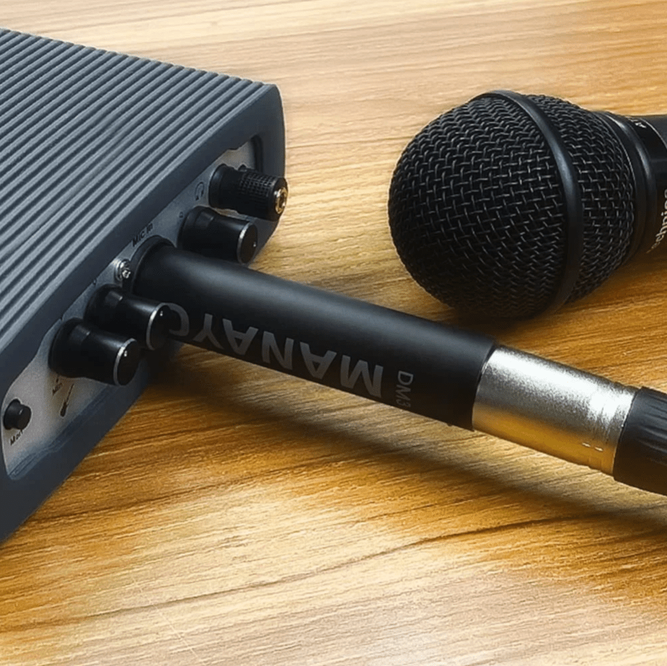


Ever since I wrote those words, I’ve been curious to see what’s inside one of these gizmos. Unfortunately, there’s no obvious way to get to the interior of my first-purchased “activator”, sold by a company called Manayo (here’s another view of the device):

and I wasn’t willing to bust it in the process of busting inside it. Fortunately, fortune more recently smiled upon me in at least three different ways: I got my hands on one of the more “popular” activators; it didn’t cost me the usual “well over a hundred dollars” (only a bit more than $40, given its “open box” status claimed by eBay retailer TradePort USA); and courtesy of two visually exposed Philips head screws, the route inside the device was seemingly obvious, painless, non-destructive and fully reversible to the functional original condition. Behold Triton Audio’s FetHead, one of a dozen conceptually related products offered by the manufacturer:

(more videos from the company here)
Look closely and you’ll see the letters “Ge” next to the product name. Your high school chemistry memory hasn’t failed you yet; they indeed stand for “Germanium”. This proliferation of the FetHead product foundation…well…I’ll let the manufacturer explain:
FetHead Germanium is high quality in-line microphone preamplifier. It provides a punchy and direct, ‘larger than life’ germanium sound for dynamic and ribbon microphones. Sounding full and rich it is reminiscent of much higher priced vintage gear, making FetHead Ge’s desirable coloration a really great addition to (interface) preamps which sound rather neutral. Our FetHead Germanium utilizes tried and true FET technology combined with a hand selected “New Old Stock” Germanium transistor to deliver 29dB’s of germanium flavored boost.
Germanium transistors were widely used in earliest transistor designs by Neve, EMI, Telefunken, and Fairchild, and have developed a reputation for a decidedly vintage mojo that remains sought after today. We created a novel hybrid circuit that consists of low noise JFETs and a hand-selected ‘new old stock’ germanium transistor to take full advantage of the “Germanium” sound and at the same time achieve the same sonic quality we are known for. A low impedance output buffer provides output drive to long cables.
Truth be told, I bought two FetHead Germaniums, both on eBay from TradePort USA, both advertised as “open box”, and both priced at just over $40. One of them, however, exhibited an audible “hissy” background noise “floor”, repeatable across the multiple microphones and audio interfaces I tried it with. User forum discussions revealed that this was a known issue: see, for example, this company representative’s post in that same discussion thread:
The transistors we use in our FetHead Germanium are selected and tested by hand.
Next to that we listen to every single FetHead Germanium before it is shipped.
Unfortunately, because we use a ‘new old stock’ germanium transistor, in rare occasions the transistor can go wrong over time.
Therefore we give a lifetime warranty on the NOS germanium transistor.
Please contact us directly at contact@tritonaudio.com to get a replacement unit.
The “lifetime warranty” promise is also documented right on the company website’s product page. Alas, my repeated efforts to contact Triton Audio via email went un-responded; perhaps the “lifetime warranty” is only valid for the original product owner? Conversely, to TradePort USA’s credit, they did respond to my outreach (promptly so, in fact) and offered a full refund, including picking up the tab for return shipping. The other unit, which I decided to keep and whose internals I’ll be sharing with you today, is still a bit “hissy” compared to its less expensive (new) Manayo predecessor showcased in November, but not egregiously so…yet, at least…
A few basics before proceeding with the dissection: first, the XLR connector:

The male connector shown at right is the variant coming out of a microphone; XLR input connectors built into audio interfaces are of the female flavor. XLR cables therefore are typically male on one end and female on the other, as are the FetHead Germanium and its ilk. Here’s a relevant Wikipedia quote:
The standard signal flow for audio in XLR connectors is that the output is a male connector and the input is female. In other words, the pins on the plug point in the direction of signal flow. Phantom power, if used, originates from the socket and flows into the plug, (the opposite direction to the signal and the normal direction for power circuits). The voltages of microphone and line level audio signals are not hazardous.
In this particular application, connections are nowadays (but weren’t always) standardized as follows:


Prior to the introduction of this standard, the wiring of pins 2 and 3 varied. The pin 2 “hot” and pin 3 “cold” convention was typically used by European and Japanese equipment manufacturers, but American companies used pin 3 “hot” and pin 2 “cold”. This caused problems when interconnecting equipment with unbalanced connections. The pin 3 “hot” convention is now obsolete but is still found on vintage equipment.
Balanced audio connections, referenced in the earlier table, are also something I’ve discussed before. In that earlier analysis, my primary focus was in their (theoretical, at least) ability to maximize audio quality through the digital-to-analog conversion and amplification links of the audio processing chain. However, I also noted:
In many professional audio applications, signals are routed from place to place via balanced cables in an effort to reduce common mode interference from radio frequency (RF) noise sources like fluorescent lights and motors. Because the voltage developed on the transmission line from RF interference is identical on both normal and inverted signal conductors, and because the balancing transformers only allow current flow when the signals are opposing, the common interference signal is canceled out.
That’s the primary reason for XLR connector (and associated balanced cabling) usage in this application: to cancel out common mode interference picked up by long cable runs acting as RF antennae.
Now a bit about phantom power, whose characteristics and (in particular) limitations were behind much of the curiosity impetus that compelled (propelled?) me to actualize this teardown’s aspiration. Here’s the introductory summary from Wikipedia’s topic entry:
Phantom power, in the context of professional audio equipment, is DC electric power transmitted through microphone cables to operate microphones that contain active electronic circuitry. It is best known as a convenient power source for condenser microphones, though many active direct boxes also use it. The technique is also used in other applications where power supply and signal communication take place over the same wires. Phantom power supplies are often built into mixing consoles, microphone preamplifiers and similar equipment. In addition to powering the circuitry of a microphone, traditional condenser microphones also use phantom power for polarizing the microphone’s transducer element.
As noted here, and as my last-November treatise also described, the presence of externally applied phantom power (alternatively self-powering via an AA battery, for example) is necessary for proper condenser microphone operation. Conversely, however, dynamic and ribbon microphones don’t need phantom power. In fact, unless they’re intentionally designed to disregard it, they might be damaged by its presence. Since the FetHead Germanium is specifically intended for use with those exact two types of microphones, such pass-through prevention is an inherent aspect of its design. This characteristic is akin to that of the company’s Phantom Blocker, which does only what its name implies, not also boosting the signal, versus the FetHeat Phantom, which delivers reduced boost for an already gain-rich condenser mic but passes phantom power on to the mic in addition to using it to fuel itself.
And how much “fuel” does phantom power offer an activator-plus-mic combo? Here’s Wikipedia’s take on the topic:
Most microphones now use the P48 standard (maximum available power is 240 mW). [editor note: that’s 5 mA max at 48 V]. Phantom powering is not always implemented correctly or adequately, even in professional-quality preamps, mixers, and recorders. In part this is because first-generation (late-1960s through mid-1970s) 48-volt phantom-powered condenser microphones had simple circuitry and required only small amounts of operating current (typically less than 1 mA per microphone), so the phantom supply circuits typically built into recorders, mixers, and preamps of that time were designed on the assumption that this current would be adequate.
The original DIN 45596 phantom-power specification called for a maximum of 2 mA. This practice has carried forward to the present; many 48-volt phantom power supply circuits, especially in low-cost and portable equipment, simply cannot supply more than 1 or 2 mA total without breaking down. Some circuits also have significant additional resistance in series with the standard pair of supply resistors for each microphone input; this may not affect low-current microphones much, but it can disable microphones that need more current.
1-2 mA isn’t much, especially in combination with any inefficiency inherent in voltage down-conversion (48V isn’t a common IC supply voltage, after all). So, one might assume that the circuitry inside the FetHead Germanium would be scant and basic, high MSRP aside. Let’s see.
Here’s the packaging that my device came in:

And here’s what it looks like outside of its cardboard tube but still within its snazzy cloth baggie, as usual (for these teardowns) also accompanied by a 0.75″ (19.1 mm) diameter U.S. penny for size comparison purposes:

Free as a bird, but still coin-accompanied (the FetHead Germanium is 3” long, 0.86” in diameter and weighs 0.12 lb):

An initial look at the other side reveals the aforementioned screws, which I promptly removed:


Let’s look first at the “female” end, i.e., the device input, fed by a microphone output:

The connector slips right out of the chassis:

“Chassis ground (cable shield)” pin 1, referencing the earlier Wikipedia-sourced diagram and accompanying table, is soldered to the black wire, while “Positive polarity terminal for balanced audio circuits (aka “hot”)” pin 2 is soldered to the red wire. Fairly rote so far, right? Rotate the connector a bit, however, and things get more interesting:


Note that pin 1 is also hardwired to both pin 3 and to the protrusion that ends up being screw-connected to the chassis. Here’s another perspective:

My trusty multimeter confirmed 0 Ω resistance between all three, as well as (a bit of foreshadowing) pin 1 of the male XLR connector on the other end:

Yes, folks, it’s true: my office go-to is an oldie-but-goodie analog Radio Shack unit:

Here’s more from Wikipedia on this particular aspect of the design:
Pin 1 has always been ground and/or shield if the cable is shielded, and many connectors connect it internally to the connector shell or case. Although covered in industry technical standards, there is still some disagreement on the best way to handle the use of pin 1 for grounding (earthing). The main controversy is whether the shell of the connector should be connected to pin 1 or the shield, or left floating.
AES standards…recommend that shells of cable-mounted connectors should never be connected to pin 1 or the shield, because inadvertent contact of the shell with another grounded surface while in use can create unwanted current paths for fault current, potentially causing hum and other noise. On the other hand, equipment containing active circuitry should always have pin 1 connected to the conductive enclosure of the equipment as close as possible to the point where the signal enters the enclosure.
The argument centers on the radio frequency shielding provided by the shell of the connector, which may be reduced if it is left floating. An alternative solution is to connect the shell to pin 1 and the shield through a small value capacitor, providing RF shielding but allowing very little audio-frequency current to flow. This capability can be built into a fixed jack or a cable terminated with XLR connectors.
Onward to the other (male) end, aka the FetHead Germanium output:

Once again, aided by needle-nose pliers to clamp onto one of the XLR pins, the connector pulled right out. Here are penny-inclusive and penniless (because I couldn’t decide which I liked better) perspectives of both sides of the PCB:


along with two edge views:


I didn’t do any desoldering or other further disassembly because I didn’t want to chance rendering the FetHead Germanium nonfunctional. And I’ve never claimed to be an analog engineer; the world of “1”s and “0”s is where I feel most comfortable. So instead of (woefully, inevitably) further pontificating, I’ll just direct you to the comments for your thoughts on parts selection, overall design, and the like. I’m obviously not getting rid of the device, and it’s easy to re-disassemble to the point where I stopped here, so I’m happy to do further (nondestructive, mind you) analysis in response to reader requests. And to further pique your curiosity, I’ll close with two other videos on other Triton Audio devices which (among other things) involved teardowns; I’ve conveniently initiated playback at the points where disassembly begins:
FetHead (an even more simple design, it seems):
FetHead Phantom (note in this case thethreewires–red, black, and blue–running from the female XLR connector on one end to the circuitry attached to the male XLR connector on the other end):
—Brian Dipert is the Editor-in-Chief of the Edge AI and Vision Alliance, and a Senior Analyst at BDTI and Editor-in-Chief of InsideDSP, the company’s online newsletter.
Related Content
Microphones: An abundance of options for capturing tonesBalanced headphones: Can you hear the difference?Designing for an uncertain futureStreaming music reception: implementation differentiationMicrophones: On-PCB options for catching tonesA microphone preamp teardown由Voice of the EngineerComponentsColumn releasethank you for your recognition of Voice of the Engineer and for our original works As well as the favor of the article, you are very welcome to share it on your personal website or circle of friends, but please indicate the source of the article when reprinting it.“A microphone preamp teardown”

Recommended
FiiO transitions: Technology evolutions

A small, dedicated battery analyzer design

CXL: The key to memory capacity in next

Battery life management: the software assistant

PCIe 4.0 SSD controller bolsters automotive storage

A sneak peek at chiplet standards

Apple’s latest product launch event takes flight