A small, dedicated battery analyzer design
- Components
- 2023-09-27 10:44:56
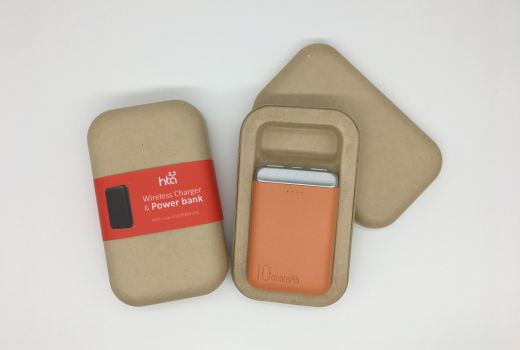
Like most things, advertised battery capacity is subject to a fair amount of specmanship [1]. The only way to know what you are buying is to test it yourself to determine if the product will meet your needs (Figure 1). The following paper presents a small, dedicated battery analyzer that I built to separate the “wishful thinking” from the “actual performance” of small batteries that might be used in a portable electronic device.
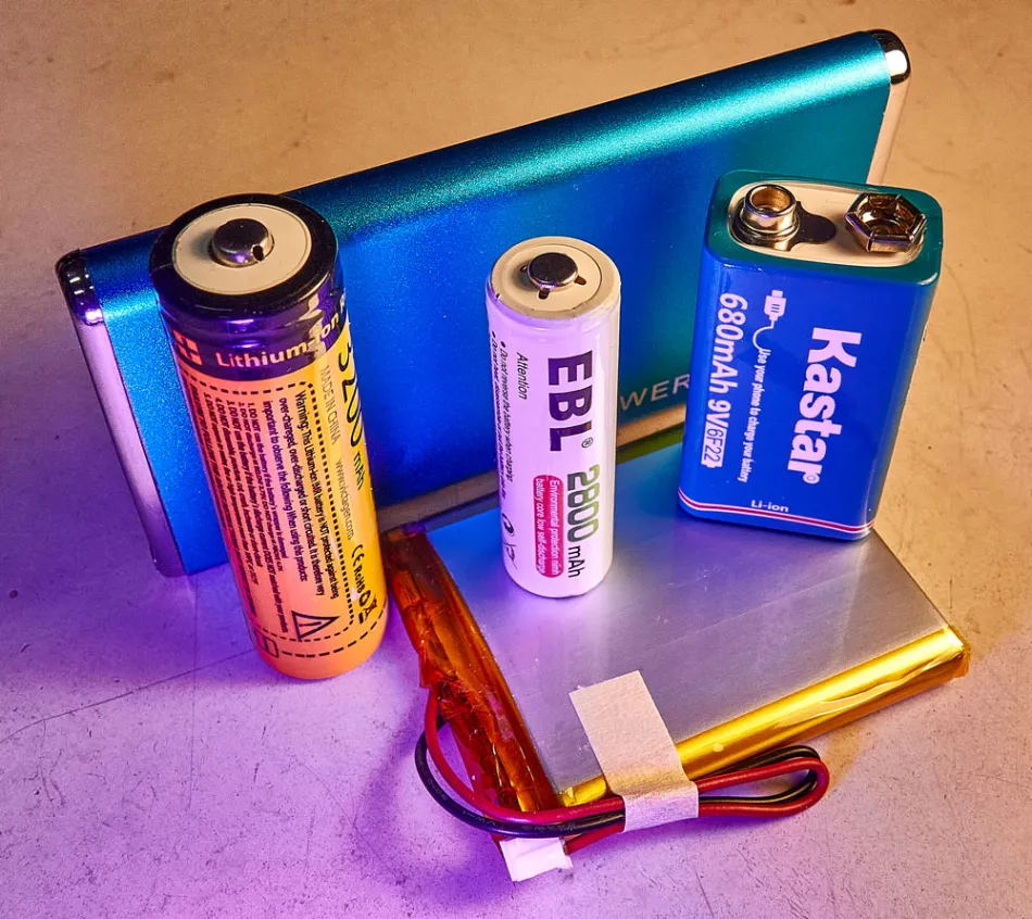
Figure 1 Batteries come in all sorts of shapes, sizes, voltages, and capacities. Bare cells with wires, familiar replaceable shapes, and complete packaged solutions. The only way to know what you are buying is to test it yourself. Source: Steve Hageman
Previous solutions


I have always had various multi-meters, programmable power supplies, and active loads laying around for power supply testing, that—coupled with some throwaway code—has allowed me to cobble together some sort of battery testing data logger. But reuse on these cobbled together setups has always been zero, and it takes an inordinate amount of time to set up and tear down these one-use systems, plus they tie up valuable lab equipment. Not ideal by any means.
A dedicated testing solution
Recently I needed to test batteries again for a new portable project I was about to start, so I decided that this was the time to re-purpose some of the junk box parts to make a dedicated battery analyzer solution, which I call the “Battery Decimator 9000”, or BD9000 for short.
The heart of the BD9000 circuit (Figure 2) is an INA250 current sense amplifier by TI [2]. This clever IC integrates the current sense resistor, thus making for a compact, accurate design.

Figure 2 The simplified block diagram of the battery analyzer, showing the major components. Source: Steve Hageman
The INA250 is used to measure the battery under test charge or discharge currents directly and provide active closed loop feedback to the current sink and source circuits. This is the only active feedback in the BD9000 design. The rest of the operation is controlled by a PIC32MZ, 32-bit microprocessor [3]. I actually used a packaged PIC32MZ in a small gum-stick footprint PCB manufactured by Micro Electronica [4]. These are nice, contained solutions that actually cost less than rounding up the processor, oscillator, LED’s, etc. for yourself. The only downside is that they do not incorporate the standard PIC programming/debug header, but since this was mounted to the BD9000 main board, I just placed it there on the layout.
The current sink and source themselves are built with large power MOSFETs. The actual current setpoints are controlled by a pair of 16-bit DACs that control the source or sink currents individually. The current sources themselves are relay isolated from each other and their outputs. This prevents some sort of catastrophic failure mode where the sink and source currents might be on at the same time and prevents unwanted leakage currents when they are off.
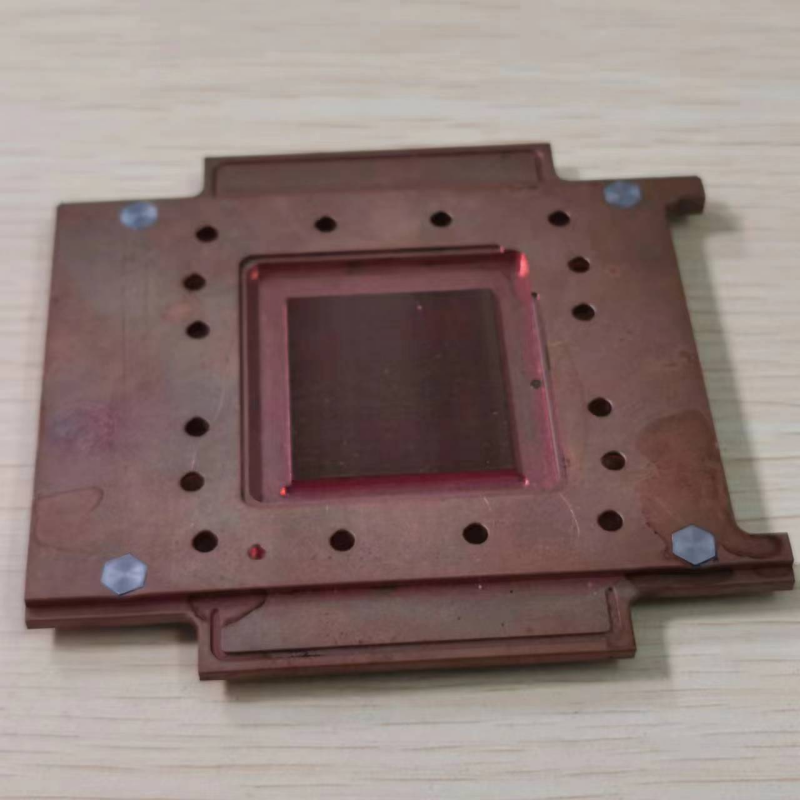
The MOSFET’s are mounted to a large heat sink that is placed in the projected chassis. There is a small fan inside the chassis also to provide cooling air flow. The fan is under microprocessor control, so it only runs when required (Figure 3).

Figure 3 The interior of the BD9000. The PCB was designed to fit a surplus chassis that I had. The cooling airflow from the microprocessor-controlled fan is directed over the heatsink where the current source and sink MOSFETs are mounted (in actual use there is a shroud placed over the fab and heatsink to funnel the air across the heatsink). Source: Steve Hageman
The BD9000 is designed to handle battery voltages from 0 to 14 volts and currents from 10 milliamps to 5 amps, but not simultaneously. With the heat sink and cooling that I used, the maximum continuous power dissipation is about 25 watts, before the heat sink temperature gets too high even with the fan running, and the thermal protection takes over to turn the current sources off to prevent “smoke”—no one likes it when an instrument goes up in smoke in the lab!
The temperature monitoring and protection is provided by having two TMP36 [5] temperature sensors. One is mounted directly to the internal heat sink, the other is brought out to the front panel to allow placement on the battery under test. The internal microprocessor then continually monitors the temperatures to provide protection during operation.
The voltage, current, and temperature readings are provided by an AD7789, 24-bit ADC [6]. This delta sigma ADC provides simultaneous 50/60 Hz rejection by onboard digital filtering, which is a plus in an application like this as I didn’t have to write any filtering routines in code.
To provide a local indication of the instrument’s operation, I decided to add a simple Adafruit 2.2 inch LCD display to the project [7]. This display provides some instant feedback as to the BD9000 state, voltage, and current readings (see Figure 4).

Figure 4 Usually, waiting for the finished application hardware to test your battery choice will be too late and may lead to costly redesigns. The BD9000 allows batteries to be tested before the target hardware is even designed. Source: Steve Hageman
Communication to the control PC is provided by the ubiquitous FTDI FT232R USB to serial port bridge IC [8]. I used the USB cable assembly part in this design as I had some in my junk box. This IC provides a USB to serial bridge link between the PIC32MZ microprocessor and the PC running the control application.
The circuit was designed with Altium Designer [9] on a 4-layer PCB that fit into the junk box chassis that I had, and fabricated by Sierra Circuits No Touch, Quick Turn process [10]. This has proven to be a very cost-effective way to quickly build things for me. The nice thing about modern PCB tools like Altium is the native 3D viewing support. This really cuts down on PCB rework as potential clearance issues can be spotted before the PCB gets fabricated (Figure 5).

Figure 5 Modern PCB layout tools like Altium reduce PCB re-spins by having native 3D support built in. This allows for potential part placement and clearance issues to be spotted before the PCB is fabricated. Source: Steve Hageman
Once the PCB came back the parts were soldered on, the chassis front panel was milled out, and everything was mounted in the chassis (Figure 6).

Figure 6 The included LCD display is used to show the state of the instrument and provide continuous monitoring of the battery voltage, current and temperature. Source: Steve Hageman
Firmware and software
The BD9000 is a virtual instrument, meaning the actual instrument interface, control, and data logging resides on a PC somewhere. The BD9000 acts as a semi-intelligent measurement front end.
The two most common types of batteries today are Lithium Ion (Li-ion) and Nickel-metal hydride (NiMH). Intelligent algorithms on how to deal with these two battery types are built into the BD9000’s firmware. The BD9000 32-bit processor controls all the hardware and contains enough “smarts” to know how to charge and discharge Li-ion and NiMH batteries without damaging anything or causing a fire.
The firmware runs as a state machine in a big loop architecture, reading the ADC and performing the required actions to monitor the state of the charge or discharge of the battery under test. A full custom mode is also available where the PC takes full control of the BD9000 hardware so any battery type can be exercised. Care must be used in this instance as the BD9000 will not actively control the battery charge and discharge, it will only monitor the internal heat sink and external battery temperature to prevent a hardware meltdown.
The firmware was written in C using the Microchip MPLAB-X IDE Ecosystem [11].
The PC software programs the various parameters in the BD9000 via the USB/serial port bridge interface. A simple terminal command parser is run on the BD9000 firmware to receive commands from the PC and to send data back to the PC via simple English readable commands.
The software then sets the BD9000 parameters, starts the charge or discharge, then monitors the progress of the instrument via querying commands (Figure 7).

Figure 7 Typical Li-ion cell charge as controlled by the BD9000. The charge starts off as a constant current until the cell voltage of 4.1 volts is reached, then the charge switches to constant voltage until the final termination at around 1.7 hours. Source: Steve Hageman
The PC can also log the data in a spreadsheet for later analysis. The PC software can be written in any language that can access a USB virtual serial port. For this application, I used Python 3 [12], for its ease of use, and excellent application libraries, but any language could be used. That’s the power of making virtual instruments like this, the ability to run on nearly any PC hardware and use nearly any programming language for the virtual control and display.
These are some of the battery parameters that can be controlled, measured, and logged with any PC:
Charge/discharge voltage profileCharge/discharge amp-hour capacityCharge/discharge temperatureDC resistance when dischargingTime varying discharge currents to simulate the target application current drawCalibration
For calibration, I wrote some Python routines that set the source and sink current control DACs to various codes, then measured the actual current with a GPIB-based 6 ½ digit DMM with a precision calibrated 10-amp current shunt.
The results were fitted to quadratic equations and then saved to the BD9000’s onboard calibration EEPROM. Upon startup, the BD9000 reads these calibration constants and uses them to get calibrated settings and readings during subsequent operation.
Overall calibrated accuracy is better than 0.5% over a 10 mA to 5 A range. The voltage readings are better than 0.25%.
Conclusion
Building a homemade instrument like this not only helps with the day-to-day work in the lab, but helps to while away the dark winter hours, and allows one to experiment and learn through experience that you might not otherwise have to opportunity to learn in your day job. I have found that these sorts of projects have proven invaluable in my electronics career, and the information learned has always been used later in a ‘real project’ somewhere down the road.
When I worked at Hewlett-Packard classic (the real HP under Bill and Dave), these sorts of projects were called “G-Jobs” (no one can really remember why now), and they went way back. Perhaps one of the first G-Job practitioners was Art Fong who was fond of buying surplus radar equipment and making “fun stuff” with it, this led to a very early police radar design [13] among many other inventions.
So, enjoy and build something fun today, what you will learn will be invaluable.
Bonus
The full schematic of the BD9000 is available on my GitHub page [14].
—Steve Hagemanhas been a confirmed “Analog-Crazy” since about the fifth grade. He has had the pleasure of designing op-amps, switched-mode power supplies, gigahertz-sampling oscilloscopes, Lock In Amplifiers, Radio Receivers, RF Circuits to 50 GHz and test equipment for digital wireless products. Steve knows that all modern designs can’t be done with Rs, Ls, and Cs, so he dabbles with programming PCs and embedded systems just enough to get the job done.
Related Content
Check battery capacity with a simple test methodBenchtop testing a battery for radiated immunityTest batteries without a voltmeter, part 2Circuit provides constant-current load for testing batteriesReferences
Specsmanship, https://en.wikipedia.org/wiki/SpecsmanshipTexas Instruments, INA250 Current Sense Amplifier, https://www.ti.com/product/INA250Microchip Technology, PIC32MZ EFH Microprocessor, https://www.microchip.com/en-us/product/PIC32MZ2048EFH064MikroElectronica, MINI32-PIC32MZ Development Board, https://www.mikroe.com/mini-32-for-pic32mzAnalog Devices, TMP36 Analog Temperature Sensor, https://www.analog.com/en/products/tmp36.htmlAnalog Devices, AD7789, 24 bit delta-sigma ADC, https://www.analog.com/en/products/ad7789.htmlAdafruit, 2.2 inch TFT display, https://www.adafruit.com/product/1480Future Technology Devices Inc, FT232RL USB Bridge, https://ftdichip.com/products/ft232rlAltium Designer, altium.comSierra Circuits – No Touch, Quick Turn PCB’s, https://www.protoexpress.com/products/no-touch/Microchip Technology MPLAB-X Development Environment, https://www.microchip.com/en-us/tools-resources/develop/mplab-x-idePython 3, python.orgArt Fong’s Police Radar G-Job, https://www.hpmemoryproject.org/timeline/art_fong/life_and_times_02.htm#chapter_15Battery Decimator Full Schematic is available at, https://github.com/Hagtronics/Battery-AnalyzerA small, dedicated battery analyzer design由Voice of the EngineerComponentsColumn releasethank you for your recognition of Voice of the Engineer and for our original works As well as the favor of the article, you are very welcome to share it on your personal website or circle of friends, but please indicate the source of the article when reprinting it.“A small, dedicated battery analyzer design”

Recommended
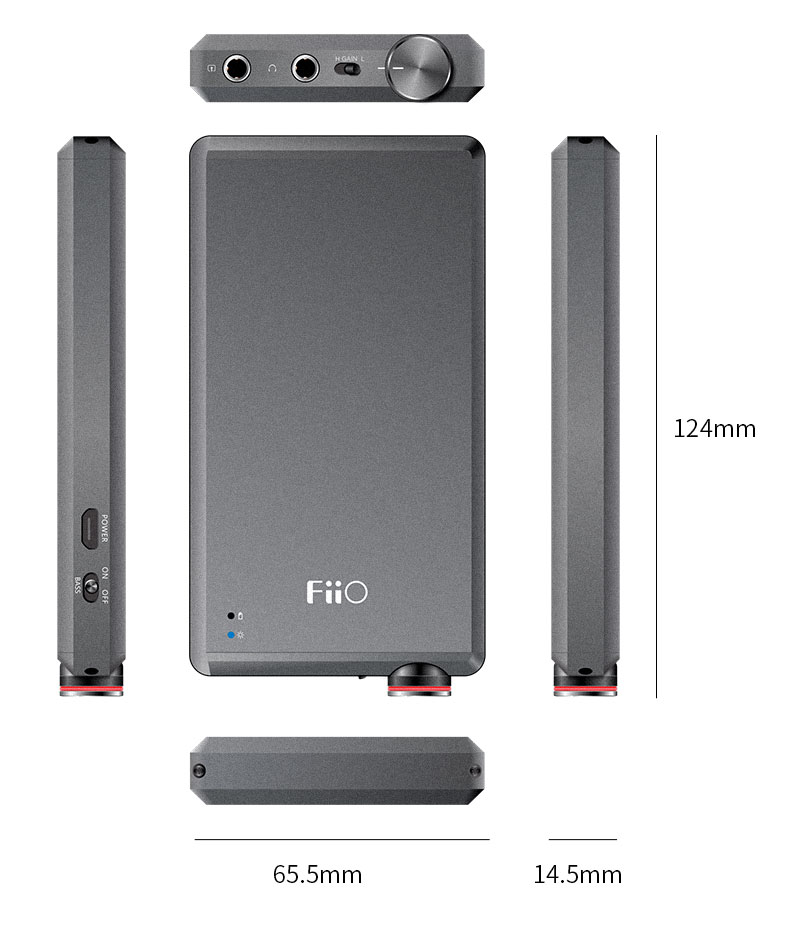
FiiO transitions: Technology evolutions
-
A small, dedicated battery analyzer design

CXL: The key to memory capacity in next
Battery life management: the software assistant
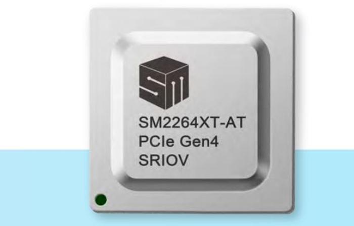
PCIe 4.0 SSD controller bolsters automotive storage

A sneak peek at chiplet standards

Apple’s latest product launch event takes flight